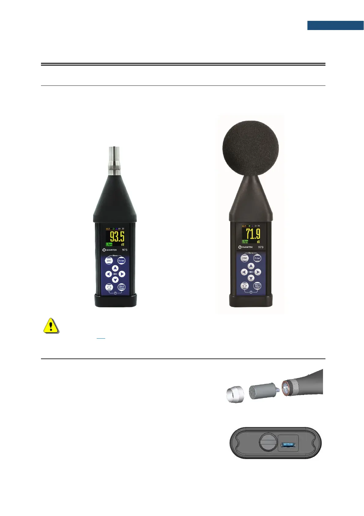
2.1 INSTRUMENT CONFIGURATIONS
The instrument's normal operating mode as SLM assumes operating with the microphone attached to
the instrument and without a windscreen. Optionally the instrument can be operated with the windscreen
attached to the microphone (see Appendix C for specification).
Note: To have measurements in accordance with the IEC 61672-1:2013 standard it is
necessary to set the appropriate compensation in the Compensation Filter screen (see
Chapter 4.7).
2.1 INPUT AND OUTPUT SOCKETS OF THE INSTRUMENT
Top cover of the instrument
The measurement Input is placed in the centre of the
instrument’s top cover. The microphone capsule with the
USB-C connector has a special locking ring with the screw.
The ring should be tightened to light resistance only. The full
description of the microphone connector is given in
Appendix C.
Bottom cover of the instrument
In the bottom cover, there is only one socket - USB. This
socket has a special protection cover held in place by a small
captive screw.