CROSS PERSONAL: Service & maintenance manual - rev. 1.1
Mechanics/Crank
assembly Timing
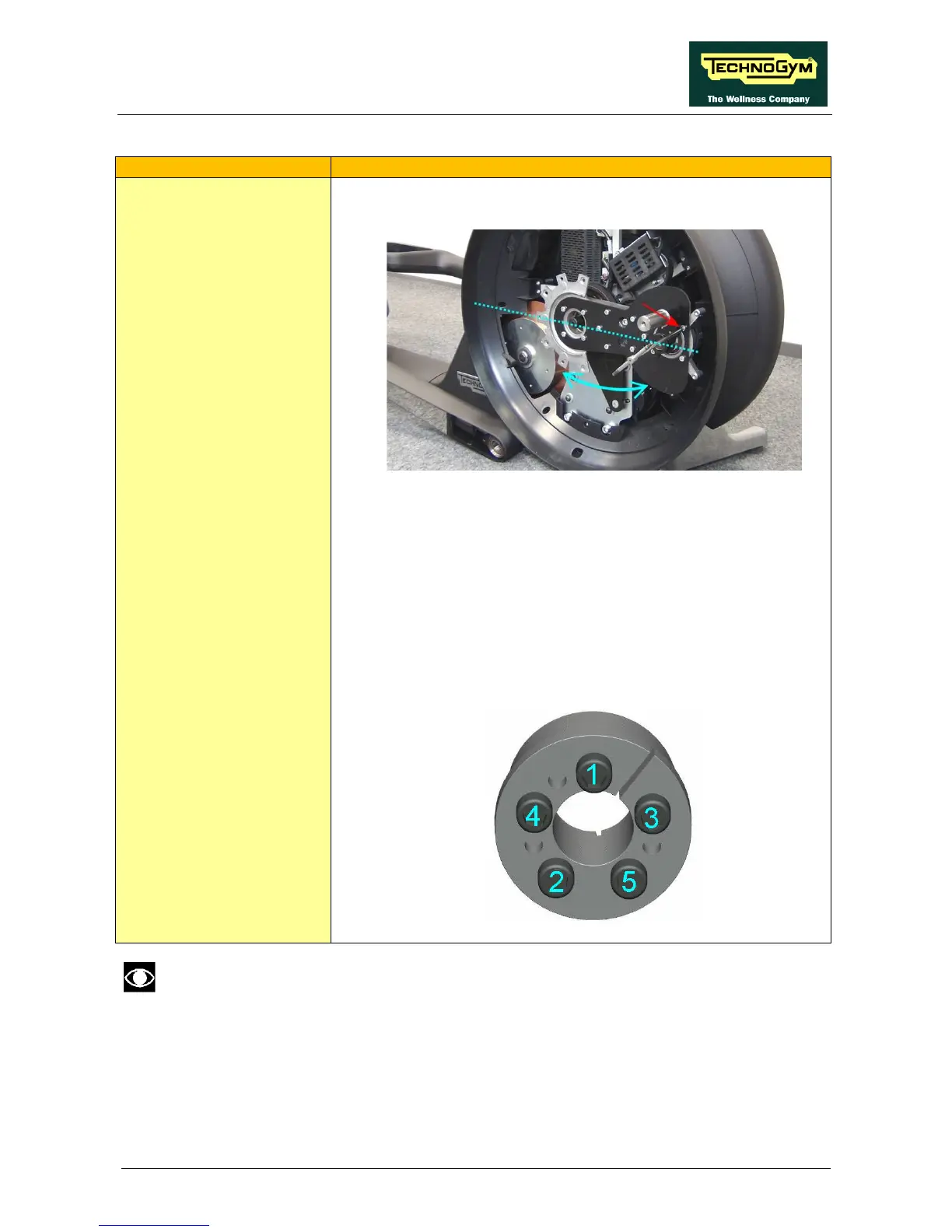
6. Anchor the timing lever, positioning the assembly as shown in
the illustration below.
• Position the assembly so that the lever/crank assembly is
parallel to the floor.
• Move the timing lever either to the right or to the left as
indicated by the blue arrow until the crank rests against a
key, positioned as illustrated.
7. Tighten the shrink disk screws.
NOTE:
tighten the screws to 16 Nm/12 lbf.ft. torque
Tighten the screws using a “star” sequence several
times to gradually achieve
the screws (see “star” sequence below).
The procedure described above can be viewed in the films showing dismantling of the
“Mechanics/Crank assembly” and the “Crank assembly belt”.