Page 6.11
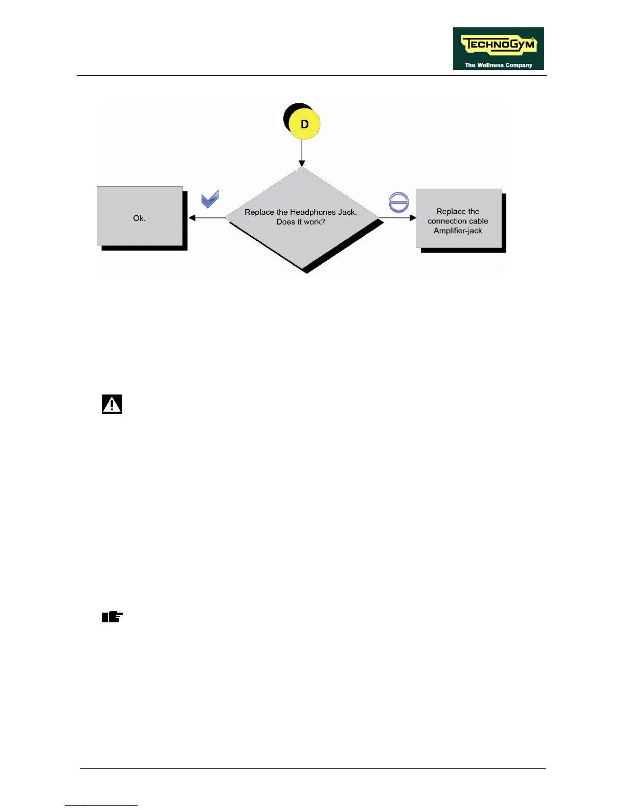
Follow the procedure step by step to correctly diagnose the problem. Take particular care with the
checks highlighted by circled numbers, which are described in detail below:
(1) Perform the test by substituting the Jack with a functioning one or disconnect it and short the
PINS 4-5 and 3-2 of the Jack connector (carriage side).
(2) Take the measurement on the J5 Audio OUT connector and check the resistance between the
earth node (on the Display) and the 4 PINS on the connector by disconnecting it.
DANGER: Take this measurement with the equipment switched off.
• PIN 1 – earth node = 1 K-Ohm;
• PIN 2 – earth node = 1 Ohm;
• PIN 3 – earth node = 1 Ohm;
• PIN 4 – earth node = 1 K-Ohm;
(3) Take the following measurements with ALTERNATING current, taking care not to short
circuit the PINS during the measurement.
• PIN 1 – earth node = 400 mVac;
• PIN 2 – earth node = 0 mVac;
• PIN 3 – earth node = 0 mVac;
• PIN 4 – earth node = 400 mVac;
WARNING: Turn the volume up to maximum.
(4) Perform the check on PINS 1 and 2 on the J5 connector and check that there is 12Vdc.
(5) Check that there is 12 Vdc on PINS 2 and 6 on the CN15 connector of the CU613 cable.