SYNCHRO EXCITE 2009: Service & maintenance manual - rev. 5.2
Pagina 7.46
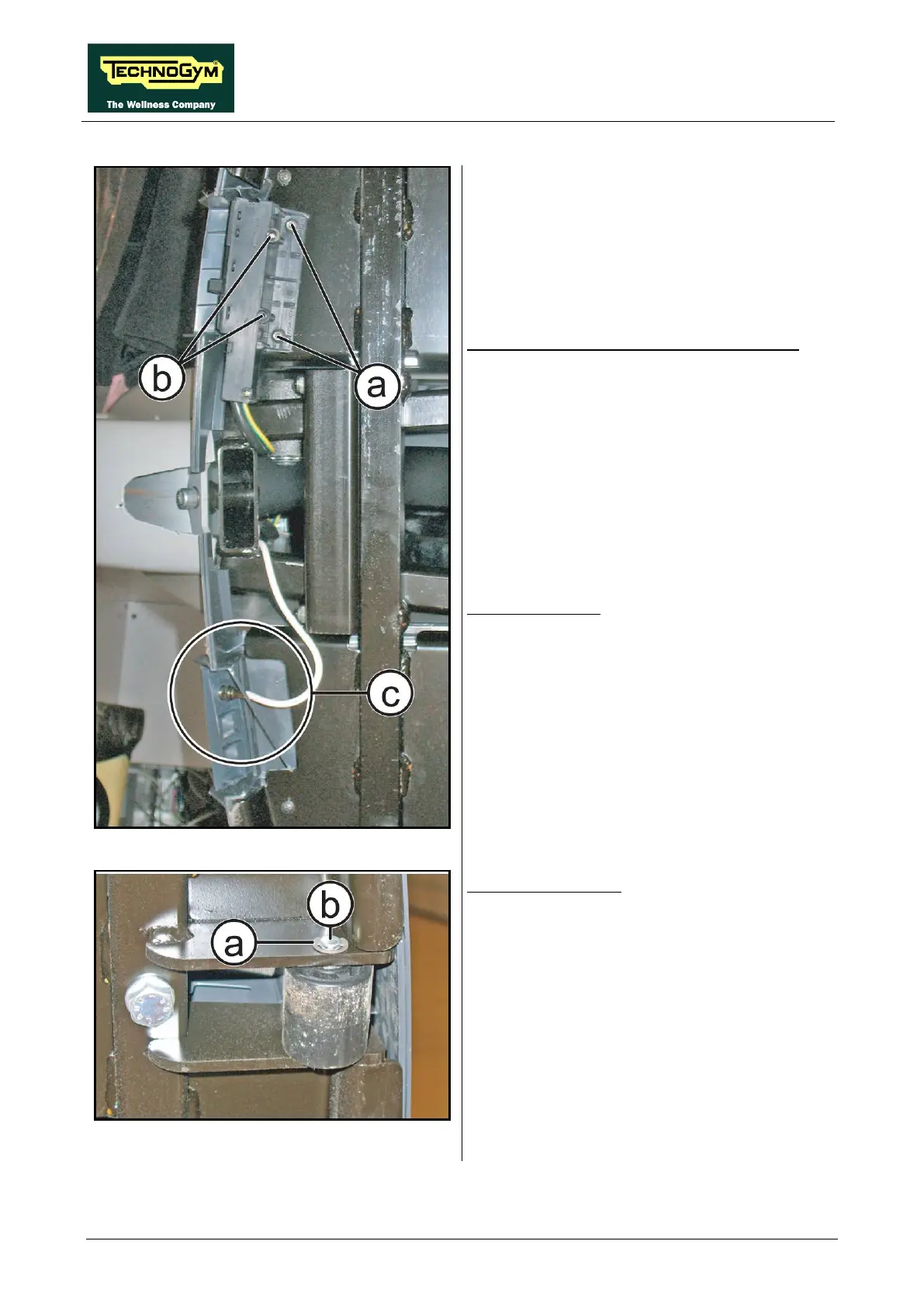
Figure 7.17-3
Power entry module (only powered models):
1. Back off the 2 screws (a), with a 4mm
hexagonal wrench.
2. Back off the 2 screws (b)
Phillips screwdriver, for remove the cover.
3. Remove the power entry module.
For WTV models:
4. Back off the antenna cable (c)
footboard casing, in case you need to replace.
Figure 7.17-4
Wheels disassembly:
1. Remove the snap ring (a) on both the sides.
2. Remove the central pin (b).
3. Remove the wheel and replace if necessary.
To reassemble the footboards, the power entry
module and the wheels, carry out the above steps
in reverse order.