6-30
Multi-Function Input Parameters
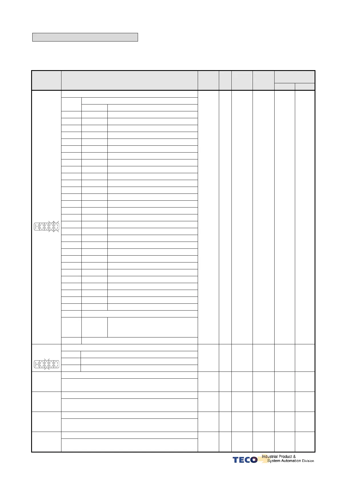
z All digital inputs D1 to D12 are programmable and can be set to one of the funhctions listed below.
z Hn 601 which includes Hn 601.0 ,Hn601.1, Hn601.2 is used for digital input 1 ( D1-1).
z Hn602 to Hn613 are used for setting digital inputs 2 to 12.( D1-2 to D1-12).
Communication
Address
Parameter Name & Function Default Unit
Setting
Range
Control
Mode
RS232 RS485
DI-1 Function
Explanation
Setting
Signal Functions
00
Null
Non-function
01
SON
Servo On
02
ALRS
Alarm Reset
03
PCNT
PI/P Switching
04
CCWL
CCW Limit
05
CWL
CW Limit
06
TLMT
External Torque Limit
07
CLR
Clear Pulse Error Value
08
LOK
Servo Lock
09
EMC
Emergency Stop
0A
SPD1
Speed 1
0B
SPD2
Speed 2
0C
MDC
Control Mode Switch
0D
INH
Position Command Inhibit
0E
SPDINV
Speed Inverse
0F
G-SEL
Gain Select
10
GN1
Electronic Gear Ratio Numerator 1
11
GN2
Electronic Gear Ratio Numerator 2
12
PTRG
Position Trigger
13
PHOLD
Position Hold
14
SHOME
Start Home
15
ORG
Home Position Reference (Origin)
16
POS1
Internal Position select 1
17
POS2
Internal Position select 2
18
POS3
Internal Position select 3
19
POS4
Internal Position select 4
1A
TRQINV
Torque Inverse
1B
RS1
Torque CW Selecting
1C
RS2
Torque CCW Selecting
1D
Reserved
1E
POS5
Internal position command
selection 5
(Tool NO. selection 5)
★
Hn601.0
Hn601.1
1F
Reserved
01 X
01
│
1F
︵
HEX.
︶
T
S
Pe
Pi
C23H 0501H
DI-1 Active Level
Setting Explanation
0 Low Active (short with IG24)
★
Hn601.2
1 High Active
0 X
0
│
1
T
S
Pe
Pi
C23H 0501H
DI-2
★
Hn602
Please refer to Hn601
002 X
001
│
11F
ALL C24H 0502H
DI-3
★
Hn603
Please refer to Hn601
003 X
001
│
11F
ALL C25H 0503H
DI-4
★
Hn604
Please refer to Hn601
008 X
001
│
11F
ALL C26H 0504H
DI-5
★
Hn605
Please refer to Hn601
00A X
001
│
11F
ALL C27H 0505H
 Loading...

