4200A-SCS Parameter Analyzer User's Manual Section 5: Configure and use a Series 700 Switching System
4200A-900-01 Rev. D/April 2020 5-9
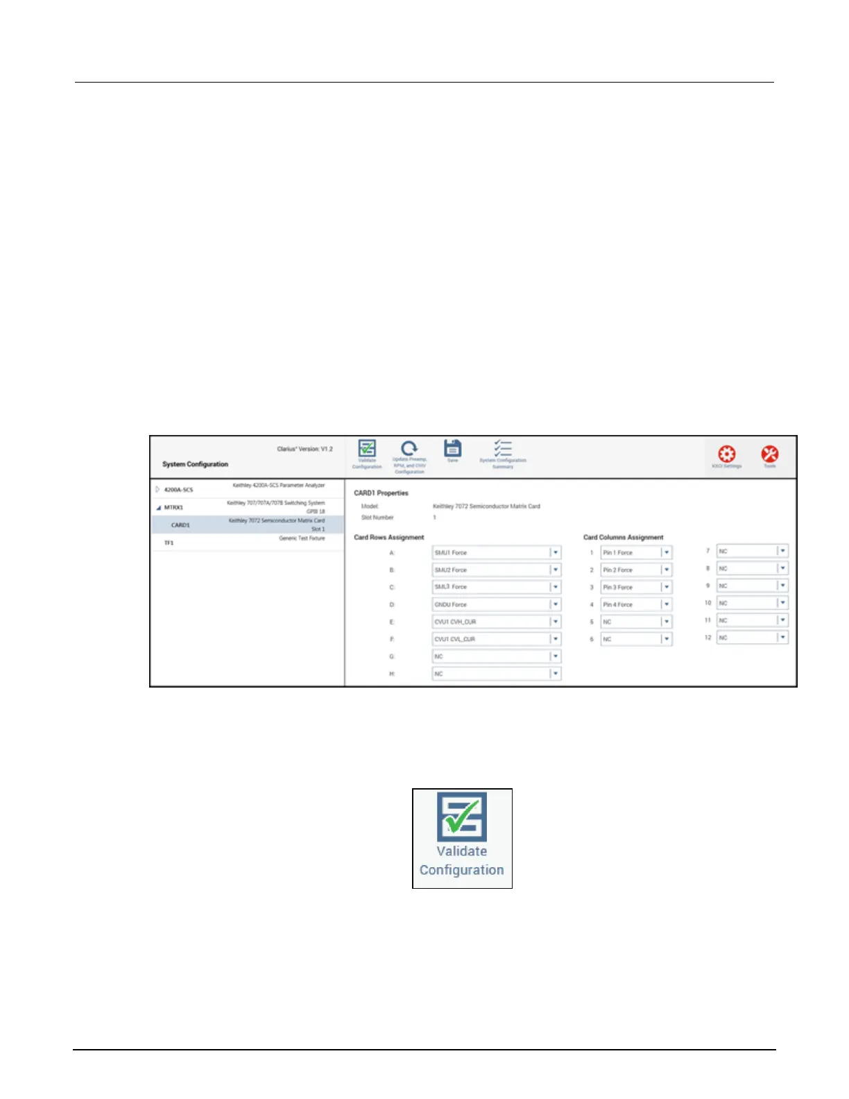
13. Select the arrow next to MTRX1 to see the settings for the 7072 Matrix Card.
14. Select CARD1.
15. Complete the Card Rows Assignments according to how you connected the instruments to the
7072. For this example, the assignments are:
▪ Row A - SMU1 Force
▪ Row B - SMU2 Force
▪ Row C - SMU3 Force
▪ Row E - GNDU Force
▪ Row G - CVU1 CVH_CUR
▪ Row H - CVU1 CVL_CUR
16. Under the Card Columns Assignment heading, designate at least the first four columns with pin
assignments that match their column number. For example, Pin 1 Force to column 1.
Figure 59: Completed Properties pane for the 7072 Matrix Card
17. From the KCon toolbar, select Validate Configuration to ensure that the switching system is
connected properly.
Figure 60: Validate Configuration icon
ООО "Техэнком" Контрольно-измерительные приборы и оборудование www.tehencom.com
 Loading...


