Appendix A: Specifications
A–2
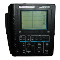
THS710A, THS720A, THS730A & THS720P User Manual
Oscilloscope Specifications (Cont.)
Inputs
Input Coupling DC, AC, or GND
Input Impedance,
DC Coupled
1 M ±1% in parallel with 25 pF ±2 pF
Maxi
u
Voltag
Overvoltage Category Maximum Voltage
tw
n Signal an
Common at Input BNC
CAT II Environment (refer to
page A–19)
300 V
RMS
CAT III Environment (refer to
page A–19)
150 V
RMS
For steady-state sinusoidal waveforms, derate at 20 dB/decade
above 100 kHz to 13 V
pk
at 3 MHz and above. Also, refer to
Overvoltage Category description on page A–19.
Maximum Voltage
Between Common and
Earth Ground at BNC
600 V
RMS
(CAT II) or 300 V
RMS
(CAT III), using rated connectors
or accessories
30 V
RMS
, 42.4 V
pk
, using noninsulated connectors or accessories
Maximum Voltage,
Channel-to-Channel
Commons
30 V
RMS
, 42.4 V
pk
, using noninsulated connectors or accessories
Channel-to-Channel
Common Mode
Rejection, typical
100:1 at frequencies ≤50 MHz, measured on MATH Ch1 – Ch2
waveform, with test signal applied between signal and common
of both channels, and with the same VOLTS/DIV and coupling
settings on each channel
Channel-to-Channel
Crosstalk, typical
≥100:1 at 50 MHz, measured on one channel, with test signal
applied between signal and common of the other channel, and
with the same VOLTS/DIV and coupling settings on each channel
Common to Chassis
Capacitance, typical
55 pF

 Loading...


