72-00-1
1
VALVE MECHANISM
Exhaust valves are faced with a special heat and corrosion-resistant material and the valve
stems are chromed for wear resistance. Oil fed to the hydraulic valve lifters, under pressure
from galleries, lubricates the lifter guide surfaces and fills the reservoirs inside the lifters. Oil
from the lifters flows through the
pushrods to the rocker arms. Each rocker arm directs a
portion of its oil through a drilled orifice toward the respective valve stem. Oil is returned to
the crankcase through the
pushrod housings, which are sealed to the cylinder head and
crankcase by rubber seals. Drain holes in the lifter guides return oil to the sump.
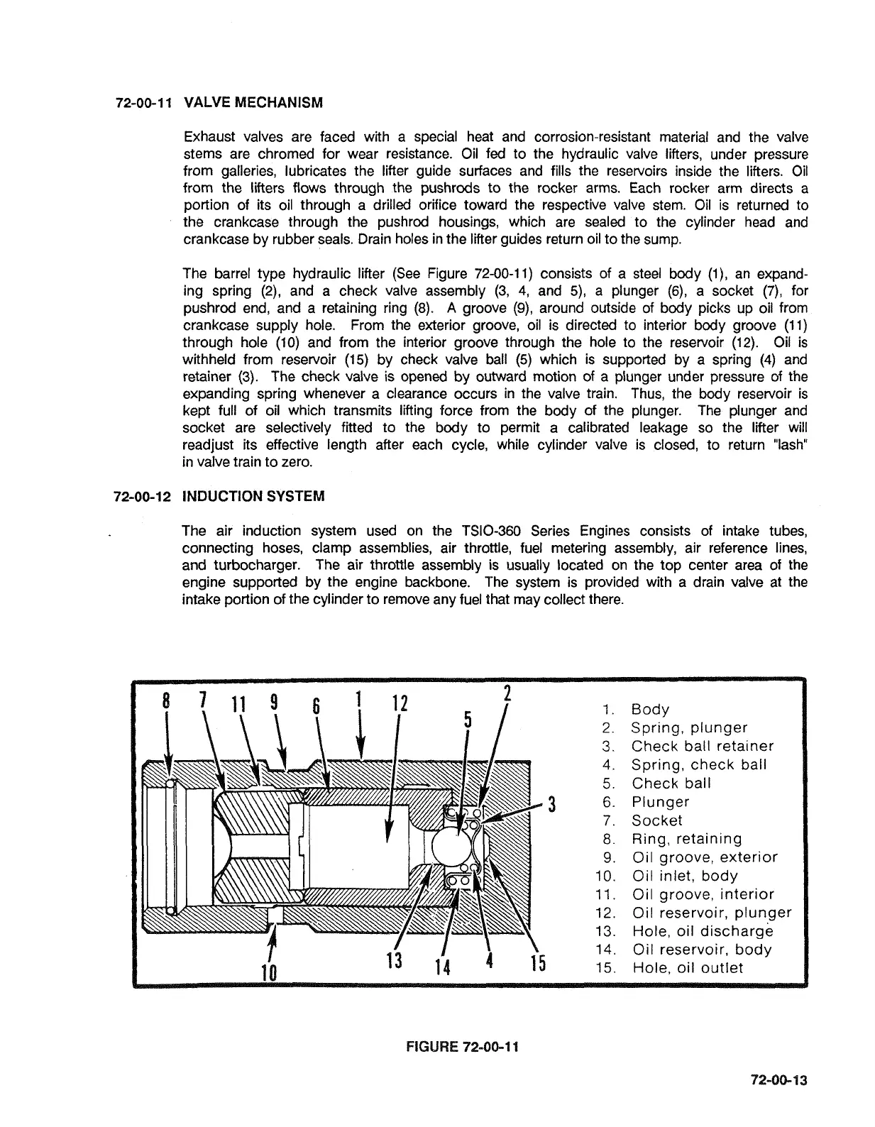
The barrel type hydraulic lifter (See Figure
72-00-1 1)
consists of a steel body
(I),
an expand-
ing spring
(2),
and a check valve assembly
(3,
4,
and
5),
a plunger
(6),
a socket
(7),
for
pushrod end, and a retaining ring
(8).
A
groove
(9),
around outside of body picks up oil from
crankcase supply hole. From the exterior groove, oil is directed to interior body groove
(I
1)
through hole
(10)
and from the interior groove through the hole to the reservoir
(12).
Oil is
withheld from reservoir
(15)
by check valve ball
(5)
which is supported by a spring
(4)
and
retainer
(3).
The check valve is opened by outward motion of a plunger under pressure of the
expanding spring whenever a clearance occurs in the valve train. Thus, the body reservoir is
kept full of oil which transmits lifting force from the body of the plunger. The plunger and
socket are selectively fitted to the body to permit a calibrated leakage so the lifter will
readjust its effective length after each cycle, while cylinder valve is closed, to return "lash"
in valve train to zero.
72-00-1 2
INDUCTION
SYSTEM
The air induction system used on the
TSIO-360 Series Engines consists of intake tubes,
connecting hoses, clamp assemblies, air throttle, fuel metering assembly, air reference lines,
and turbocharger. The air throttle assembly is usually located on the top center area of the
engine supported by the engine backbone. The system is provided with a drain valve at the
intake portion of the cylinder to remove any fuel that may collect there.
2.
Spring, plunger
3.
Check ball retainer
4.
Spring, check ball
5.
Check ball
8.
Ring, retaining
9.
Oil groove, exterior
10.
Oil inlet, body
11.
Oil groove, interior
12.
Oil reservoir, plunger
13.
Hole, oil discharge
14.
Oil reservoir, body
FIGURE
72-00-1
1
 Loading...

