- 7 -
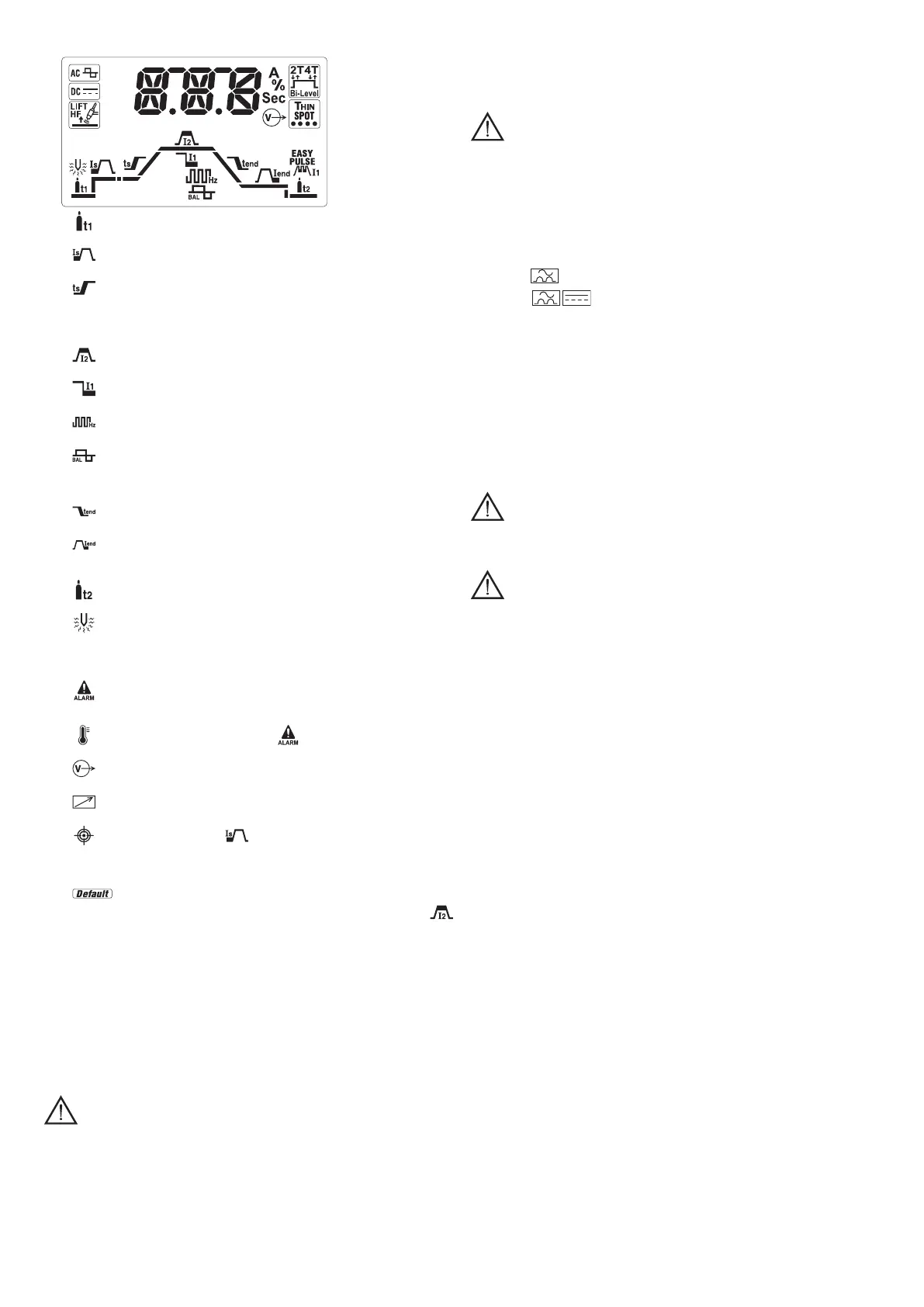
Inparticular,inTIG,theparametersthatcanbechangedare:
- pre-gas time of safety gas ow before starting welding (0-10 seconds
adjustment).
-
initial current maintained for a set time in 2T (50msec) and for the time the
push-button is pressed, in 4T (0-100% adjustment).
-
initial ramp time of the current from value I
s
to I
2
(0.1-10 seconds
adjustment). In OFF ramp not present.
N.B.: parameters I
s
and T
s
can also be modied with the pedal remote
command. Adjustment, however, must be made before activating the
commanditself.
-
main welding current, in PULSED and Bi-Level mode is the current at
higher level (output current in Amperes).
-
basic current, in PULSED and Bi-Level mode is the value which can be
alternated with the main one during welding (adjustment in Amperes).
-
pulsation frequency and for AC/DC models in TIG AC it represents the
frequency of the welding current (adjustment in Hertz).
-
balance percentage, in PULSED mode is the ratio between the time in
which the current is at the highest level and the total pulsation period, for AC/DC
models in TIG AC it represents the ratio between the time with positive current
and the time with negative current.
-
nal ramp time of the current from value I
2
to I
end
(0.1-10 seconds
adjustment). In OFF ramp not present.
-
nal current, in 2T it is the current maintained after the nal ramp if the
ramp time is over zero, in 4T it is the current maintained after the nal ramp for
the entire time in which the torch push-button remains pressed.
-
post-gas time of safety gas ow starting from welding stoppage (0-10
seconds adjustment).
-
pre-heating energy, if installed, only for AC/DC models in TIG AC adjusts
pre-heating of the electrode to facilitate start-up (2.6-53 A*Sec adjustment). In
OFF pre-heating not present.
Otherexplanatoryiconsonthedisplay:
-
warning/alarm, in general combined with the code indicated on the display,
drawing attention to possible anomalies/automatic protection activated on the
welding machine.
-
thermal protection, combined with and the code on the display,
warning the condition of internal heating limits has been reached.
-
active output, indicates voltage is present (power enabled) in the output
sockets of the welding machine.
-
remote command, indicates connection and control is active on the remote
command.
-
position pointer, in 4T with under a preset value, it indicates setting of
a minimum initial current that makes the welding arc visible with push-button
pressed. This allows precise selection of the starting point of the welding (if the
initial current is set beyond a certain limit the function automatically disables).
-
factory parameters, indicates setting of all the parameters at a preset
value useful for wide-ranging operativity. The user can set the main current
as wished to alter the other automatic settings.
It is possible to re-activate this condition at any time by switching off and back on
the welding machine with the push-button on the multi-function knob (FIG. D - 5c)
pressed.
Explanatoryalarmmessagesonthealphanumericaldisplay(FIG.D-5d):
- AL.1 : the primary circuit protection thermal switch has been triggered (if
installed).
- AL.2 : the secondary circuit protection thermal switch has been triggered.
- AL.3 : power line overvoltage protection has been triggered.
- AL.4 : power line undervoltage protection has been triggered.
- AL.8 : auxiliary voltage out of range.
Resetting is automatic when the reason for alarm activation stops.
5.INSTALLATION
WARNING! CARRY OUT ALL INSTALLATION OPERATIONS AND
ELECTRICAL CONNECTIONS WITH THE WELDING MACHINE COMPLETELY
SWITCHEDOFFANDDISCONNECTEDFROMTHEPOWERSUPPLYOUTLET.
THEELECTRICALCONNECTIONS MUSTBEMADEONLYANDEXCLUSIVELY
BYAUTHORISEDORQUALIFIEDPERSONNEL.
5.1PREPARATION(FIG.P)
Unpack the welding machine, assemble the separate parts contained in the package.
5.1.1Assemblingthereturncable-clamp(FIG.E)
5.1.2Assemblingtheweldingcable-electrodeholderclamp(FIG.E)
5.2POSITIONOFTHEWELDINGMACHINE
Choose the place to install the welding machine so that the cooling air inlets and
outlets are not obstructed (forced circulation by fan, if present); at the same time make
sure that conductive dusts, corrosive vapours, humidity etc. will not be sucked into
the machine.
Leave at least 250mm free space around the welding machine.
WARNING! Position the welding machine on a at surface with
sufcientcarryingcapacityforitsweight,topreventitfromtippingormoving
hazardously.
5.3CONNECTIONTOTHEMAINPOWERSUPPLY
- Before making any electrical connection, make sure the rating data of the welding
machine correspond to the mains voltage and frequency available at the place of
installation.
- The welding machine should only be connected to a power supply system with the
neutral conductor connected to earth.
- To ensure protection against indirect contact use residual current devices of the
following types:
- Type A (
) for single phase machines;
- Type B (
) for 3-phase machines.
- In order to satisfy the requirements of the EN 61000-3-11 (Flicker) standard we
recommend connecting the welding machine to the interface points of the main
power supply that have an impedance of less than:
Zmax = 0.234 Ohm (1/N/PE 230V) 200A DC
- The IEC/EN 61000-3-12 Standard does not apply to the welding machine.
If the welding machine is connected to an electrical grid, the installer or user must
make sure that the machine can indeed be connected (if necessary, consult the
company that manages the electrical grid).
5.3.1Plugandoutlet
Connect a normalised plug (2P + P.E) (1~); (3P + P.E) (3~) - having sufcient capacity-
to the power cable and prepare a mains outlet tted with fuses or an automatic circuit-
breaker; the special earth terminal should be connected to the earth conductor (yellow-
green) of the power supply line. Table (TAB.1) shows the recommended delayed fuse
sizes in amps, chosen according to the max. nominal current supplied by the welding
machine, and the nominal voltage of the main power supply.
WARNING!Failuretoobservetheaboveruleswillmakethe(Class1)
safetysysteminstalledbythemanufacturerineffectivewithconsequentserious
riskstopersons(e.g.electricshock)andobjects(e.g.re).
5.4CONNECTIONOFTHEWELDINGCABLES
WARNING!BEFOREMAKINGTHEFOLLOWINGCONNECTIONSMAKE
SURETHEWELDINGMACHINEISSWITCHEDOFFANDDISCONNECTEDFROM
THEPOWERSUPPLYOUTLET.
Table (TAB. 1) gives the recommended values for the welding cables (in mm
2
)
depending on the maximum current supplied by the welding machine.
5.4.1TIGwelding
Connectingthetorch
- Insert the torch current cable into the appropriate quick terminal (-). Connect the
three-pin connector (torch button) to the appropriate socket. Connect the torch gas
pipe to the appropriate connector.
Connectingtheweldingcurrentreturncable
- This is connected to the piece to be welded or to the metal bench on which it rests,
as close as possible to the joint being made.
This cable is connected to the terminal with the (+) symbol.
Connectingthegasbottle
- Screw the pressure reducing valve to the gas bottle valve, rst inserting the special
reduction accessory supplied when argon gas is used.
- Connect the gas inow hose to the pressure reducing valve and tighten the hose
clamp supplied.
- Loosen the ringnut for adjusting the pressure reducing valve before opening the
valve on the bottle.
- Open the valve on the bottle and adjust the quantity of gas (l/min) according to the
suggestions for use given in the table (TAB.4); if it is necessary to adjust the gas
ow during welding this should always be done by adjusting the ring nut on the
pressure reduction valve. Make sure there are no leaks in the piping and connectors.
WARNING!Alwaysclosethegasbottlevalveattheendofthejob.
5.4.2MMAWELDING
Almost all coated electrodes are connected to the positive pole (+) of the power
source; as an exception to the negative pole (-) for acid coated electrodes.
Connectingtheelectrode-holderclampweldingcable
On the end take a special terminal that is used to close the uncovered part of the
electrode.
This cable is connected to the terminal with the symbol (+)
Connectingtheweldingcurrentreturncable
This is connected to the piece being welded or to the metal bench supporting it, as
close as possible to the join being made.
This cable is connected to the terminal with the symbol (-)
Warnings:
- Turn the welding cable connectors right down into the quick connections (if present),
to ensure a perfect electrical contact; otherwise the connectors themselves will
overheat, resulting in their rapid deterioration and loss of efciency.
- The welding cables should be as short as possible.
- Do not use metal structures which are not part of the workpiece to substitute the
return cable of the welding current: this could jeopardise safety and result in poor
welding.
6.WELDING:DESCRIPTIONOFTHEPROCEDURE
6.1TIGWELDING
TIG welding is a welding procedure that exploits the heat produced by the electric arc
that is struck, and maintained, between a non-consumable electrode (tungsten) and
the piece to be welded. The tungsten electrode is supported by a torch suitable for
transmitting the welding current to it and protecting the electrode itself and the weld
pool from atmospheric oxidation, by the ow of an inert gas (usually argon: Ar 99.5)
which ows out of the ceramic nozzle (FIG.G).
To achieve a good weld it is absolutely necessary to use the exact electrode diameter
with the exact current, see the table (TAB.3).
The table on the covering of the machine suggests the approximate current values to
use in the various material thicknesses with reference to DC welding of mild steel or