Aligna
®
4D User Manual
61 / 84
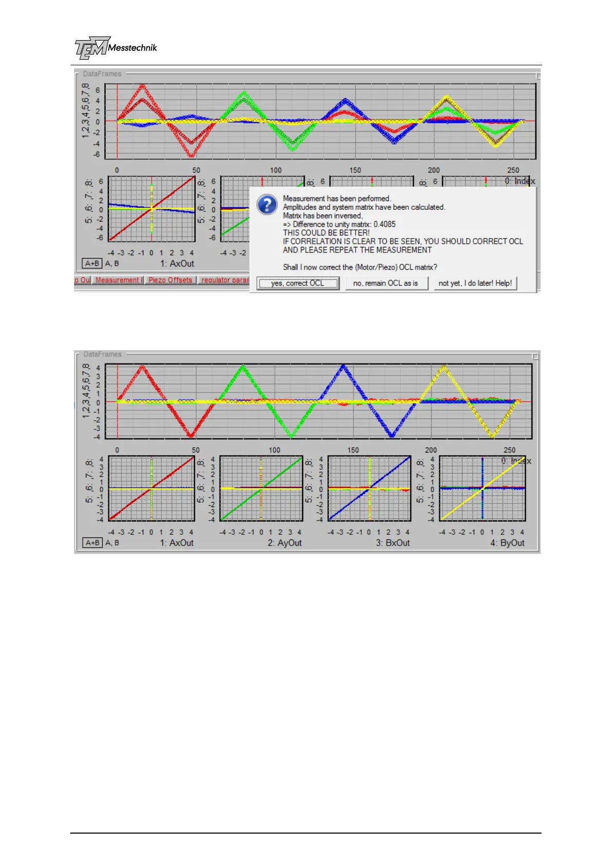
The signs are correct now; however, there are remaining errors in the gain values. The system
will calculate an improved OCL, again.
In the next measurement, you get a nearly perfect result:
The measured values (dark) are nearly identical with the set values (bright).
NOTE: This movement is done WITHOUT the servo loops! This is called "feed-forward". If
the servos ("feed-back") will be switched on later, they will compensate for the (very small)
residual errors. That means: The feed-forward will compensate 90%...99% of the 4D error
by the matrix calculation, due to the "knowledge" of the opto-mechanical system. You can
say: "by the experience with the setup". As a result, the feed-back loop is just responsible
for a very small amount, let's say 5%. Thus, the system will be 20-times faster, compared
to the situation, that the feed-back loop has to do the whole job!
The matrix now contains the information on the mirror motor properties, in scaling and sign of
movement, distances between the mirrors and the detector, properties of the detectors like
sensitivity, scaling, focusing, coupling of X and Y, or sign changes, by inserted mirrors, tele-
scopes, non-planar beam path, etc.
NOTE: The examples here are achieved with a simple system (cw laser pointer with small
fluctuations, short distances, enough test beam intensity, Aligna 60 mirror mounts, which
have high mechanical resolution etc.) If conditions are worse (laser with large pointing
fluctuation, large distances, etc., the curves may be much noisier. However, it can work as
well (not as fast as with an "ideal" system), because the OCL only defines the "feed-