Aligna
®
4D User Manual
62 / 84
forward" control. The "feed-back" loop, performed by the servos, is responsible for the re-
sidual errors of the feed-forward control.
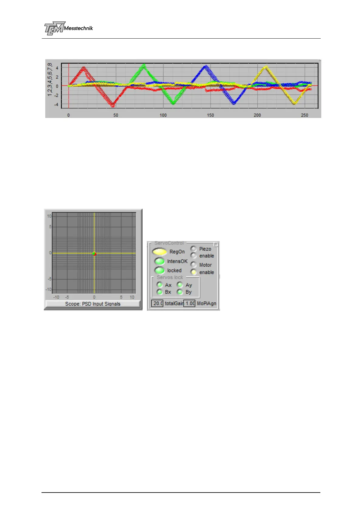
Measurement with larger distances:
Higher deviation from ideal curves, but nevertheless working well.
10.3.10.7 Switching on the (Four) Motorized Servos
Now the system “learned” the properties of your opto-mechanical setup (including distances
between the mirrors, distances to the PSDs, orientation of the mirrors and detectors, etc.), and
you can switch on the regulation (click the “RegOn” button). The red and the green spot (angle
and position) of the X/Y scope will immediately go the center, which means, the beam is 4D
stabilized to the beam path, given by the optical axis of the 4D detector.
Note: The matrix is stored inside the micro controller. It can now work as a stabilization
system in an autarkic way, without the need of a connected PC. The PC is just needed for
“learning”, for visualization, for error message display, for scanning, etc.
The servos need enough intensity (“IntensOK” lamp is lit green).
Depending on the "quality" of the OCL learning, it may be necessary to reduce the "total gain"
value in the case the motors are oscillating, moving permanently, and maybe even enlarging
their movement. In this case, switch off the regulator, select a distinct smaller "total gain" by a
factor of 3 or 10 or so, and try again.
For testing the stabilization function, you can bend the laser mount or any of the mirror mounts
with your finger tips and observe the servos working, putting both angle (red dot) and position
(green dot) back to the 0,0,0,0 4D pointing position.
10.3.10.8 Optimization of Servo Gain and other Servo Parameters
Increase parameter "totalGain" to make the servo loop faster. Decrease the parameter to
avoid oscillations or overshoots.
(A more detailed description of manual and automatic optimizing of the total gain and other
servo parameters is in preparation...)