LLZ 421
Repair Operation and Maintenance
ILS 420
6−38 Ed. 01.10SOAC
Loading the specific data for changing from location LG−M to LG−A:
a) Replacing the board from location LG−M to LG−A. Switch on equipment with TX1 and TX2.
b) Open the Station Configuration dialog (see Annex ’PC User Program−specific Procedures’). After
confirmation of the settings, the configuration is loaded to the LG−A board.
Download previously stored or noted equipment data to the board (with ADRACS ’Data’ submenu
’Up−/Download Data’, resp. with MCS ’Snapshot’ submenu ’Open’). Perform readjustment pro-
cedure of transmitter and monitor.
Loading the specific data for changing from location LG−A to LG−M:
a) Replacing the board from location LG−A to LG−M. Switch on equipment with TX1 and TX2.
b) Open the Station Configuration dialog (see Annex ’PC User Program−specific Procedures’). Se-
lect ’Farfield (Ch. 5) is executive: No’. Confirm the setting.
c) Open the Station Configuration dialog (see Annex ’PC User Program−specific Procedures’). Se-
lect ’Farfield (Ch. 5) is executive: Yes’. Confirm the setting.
d) Download previously stored or noted equipment data to the board (with ADRACS ’Data’ submenu
’Up−/Download Data’, resp. with MCS ’Snapshot’ submenu ’Open’). Perform readjustment pro-
cedure of transmitter and monitor (calibration and normalization of all channels).
6.6.3.5 VAM−ILS Option, Line Input Calibration
The VAM is set to 10 dB gain as default. To adapt this gain to expected input levels refer to 6.6.5/8.
6.6.4 Test after Repair
After repair and mechanical check, the installation is switched on as normal. The necessary adjust-
ments indicated in the Table in Fig. 6−7 have to be performed. All parameters have to be within limits
and the system state indicates NORMAL again. The system is then operable.
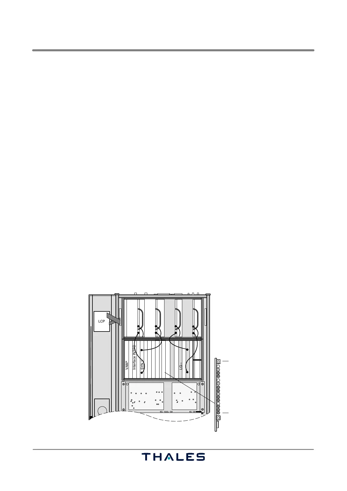
NOTE: If the LED "Switch Fail" (Fig. 6−10) at the ECU is flashing, check correct fitting of subas-
semblies in the BP−MODPA and BP−Digital.
LCP
SYN 1
VAM*
Interface INTFC
LG−A 2
SYN 2
LG−M 1
LG−M 2
MOD/PA 1/1
MOD/PA 1/2
Modem*
Modem*
ECU
LG−A 1
J20 J21
ECU
Reset Board
Switch Fail
W35
W33 W34 W36
MOD/PA 2/1
MOD/PA 2/2
Fig. 6−10 Location of "Switch Fail" indication at ECU