LLZ 421
Operation and Maintenance Operation
ILS 420
3−19Ed. 01.10
SOAC
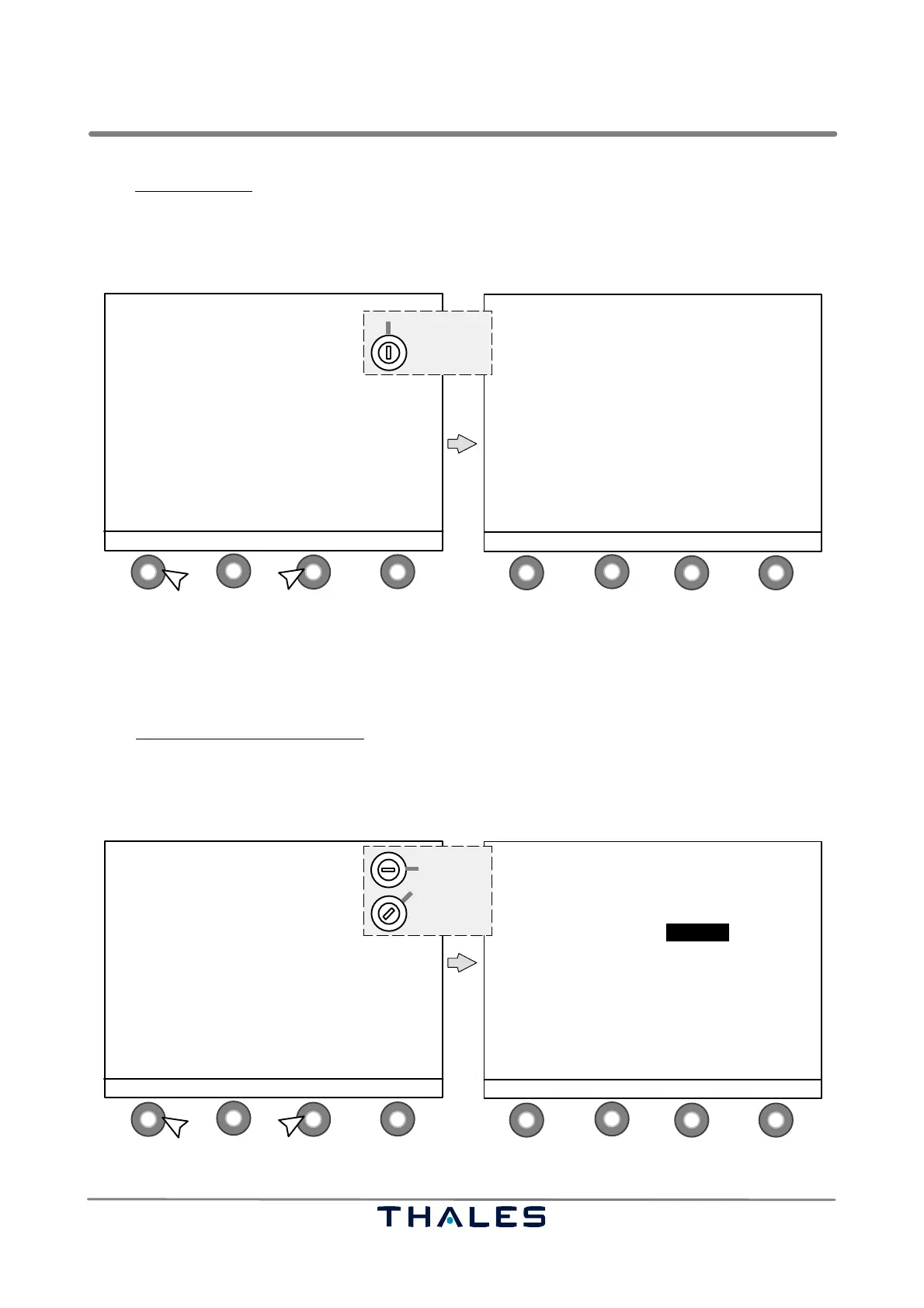
In the Waveform Data window the following button definitions are (key switch position ’REMOTE’) :
− S1 MENU to return to the Menu List window
−S2 blank not used in this window
−S3 blank not used in this window
−S4 blank not used in this window
1
4
2
3
1
4
2
3
MENU LIST
−−−−−−−−−−−
SHOW ALERTS
MONITOR QUICK ACCESS
MONITOR EXEC & FIELD all parameters
MONITOR STANDBY all parameters
POWER SUPPLIES
> WAVEFORM DATA
POWER AMPLIFIER DATA (CRS and CLR)
MTBO
CONFIGURATION DATA
ENTER ↑ SELECT ↓ STATUS
REMOTE
1.2.
Key switch
control buttons (S)
AERIAL: TX1 / ON IDENT:MORSE
LOAD: TX2 / ON
CRS
TX1 TX2
CRS CSB POWER W 26.16 25.29
CRS CSB DDM % 0.00 0.00
CRS CSB SDM % 40.05 40.11
CRS SBO LEVEL % 60.00 60.00
CRS SBO PHASE ° 90 90
MOD 1020Hz % 8.00 8.00
IDENT MORSE MORSE
MENU
Fig. 3−19 WAVEFORM DATA select and Waveform Data window (example)
For adjustments during flight check, the LCP list item FLIGHT CHECK is visible and available in the
MENU LIST in key switch position ’LOCAL’ or ’MAINTENANCE’ (see Fig. 3−20). This feature is used
for quick access to some settings. The feature needs three steps (3 windows) to perform the settings.
In the Active Waveform Data Course
window (1st step) the following button definitions are used:
− S1 CLEARANCE to go to the Active Waveform Data Clearance window
−S2 ↓ to scroll parameters downwards; selected value with black background
−S3
→ to switch to parameter right; selected value with black background
− S4 MODIFY to select the parameter to be adjusted (see Fig. 3−21)
1
4
2
3
1
4
2
3
MENU LIST
−−−−−−−−−−−
SHOW ALERTS
CONTROL
MONITOR QUICK ACCESS
MONITOR EXEC & FIELD all parameters
MONITOR STANDBY all parameters
POWER SUPPLIES
> WAVEFORM DATA / FLIGHT CHECK
POWER AMPLIFIER DATA (CRS and CLR)
MTBO
CONFIGURATION DATA
ENTER ↑ SELECT ↓ STATUS
LOCAL
MAINTENANCE
1.2.
Key switch
control buttons (S)
AERIAL: TX1 / ON IDENT:MORSE
LOAD: TX2 / ON
CRS
TX1 TX2
CRS CSB POWER W 26.16 25.29
CRS CSB DDM % 0.00 0.00
CRS CSB SDM % 40.05 40.11
CRS SBO LEVEL % 60.00 60.00
CRS SBO PHASE ° 90 90
MOD 1020Hz % 8.00 8.00
IDENT MORSE MORSE
CLEARANCE ↓ SELECT → MODIFY
Fig. 3−20 FLIGHT CHECK select and Active Waveform Data CRS window, 1st step (example)