LLZ 421
Operation and Maintenance Operation
ILS 420
3−1Ed. 01.07
SOAC
CHAPTER 3
OPERATION
3.1 GENERAL
Standard operation is normally carried out via a remote control interface (Modem) with the user pro-
gram ADRACS installed on a PC. For local operation basic operation is available at the local control
panel (LCP). It provides access to main status indication, equipment status and measurement data
and manual controls (switch commands) for basic control functions. The alignment procedure and
the maintenance are performed with a locally connected PC which is connected to connector Local
PC on top of the cabinet.
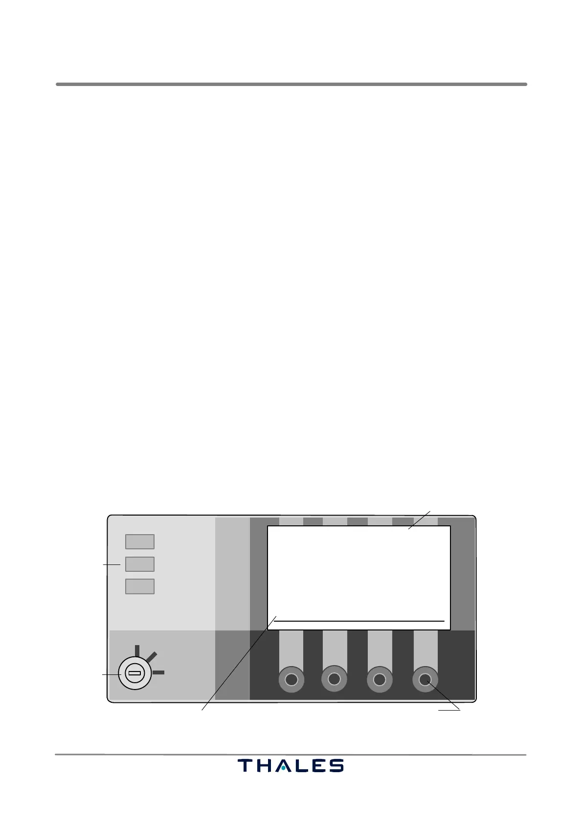
3.2 LOCAL CONTROL PANEL (LCP)
See Fig. 3−1.
The LCP located in the front door of the cabinet provides following indications and controls:
− three indication lamps for the main status of the system (ALARM, WARNING, NORMAL)
− a menu driven liquid crystal display (LCD) screen (16 lines x 40 characters) for indication of station
name and type, status of monitor(s) and transmitter(s) and measurement data
− four control buttons (S1 to S4) to perform simple activities in the control menu like change−over
or disconnect the transmitter(s); the function of buttons is defined by software and assigned in the
LCD screen.
− a key−lock switch to select three operational modes of the station REMOTE, LOCAL, MAINTE-
NANCE, which defines operation from remote site or local at the cabinet or operation in mainte-
nance mode; the actual mode is presented on the LCD screen.
A test of the three indication lamps on the LCP is provided by pressing buttons S2 and S3 simulta-
neously. The meaning of the indications, buttons and the key−lock switch on the LCP is described
in the following sections.
NOTE: A buzzer sounds for a short time whenever one of the control buttons is pressed.
REMOTE
LOCAL
MAINTENANCE
ALARM
WARNING
NORMAL
key−lock
switch
main status
indication
control buttons
liquid crystal display screen
MENU MONITOR CONTROL
S1 S2 S3
S4
ILS 420 LOCALIZER
−−−−−−−−−−−−−−−−−−−
TX 1: ON TX 2: ON
STANDBY MAIN
LOAD AERIAL
146 hrs. 145 hrs.
Monitor: −−1−− −−2−−
Executive: NORMAL NORMAL
Farfield: NORMAL NORMAL
Standby: NORMAL NORMAL
Maintenance Alert RWY: ON
ALERTS
appears flashing if maintenance alert
Fig. 3−1 Local Control Panel, example
Ed. 07.08