LLZ 421
Installation Operation and Maintenance
ILS 420
2−8 Ed. 01.04SOAC
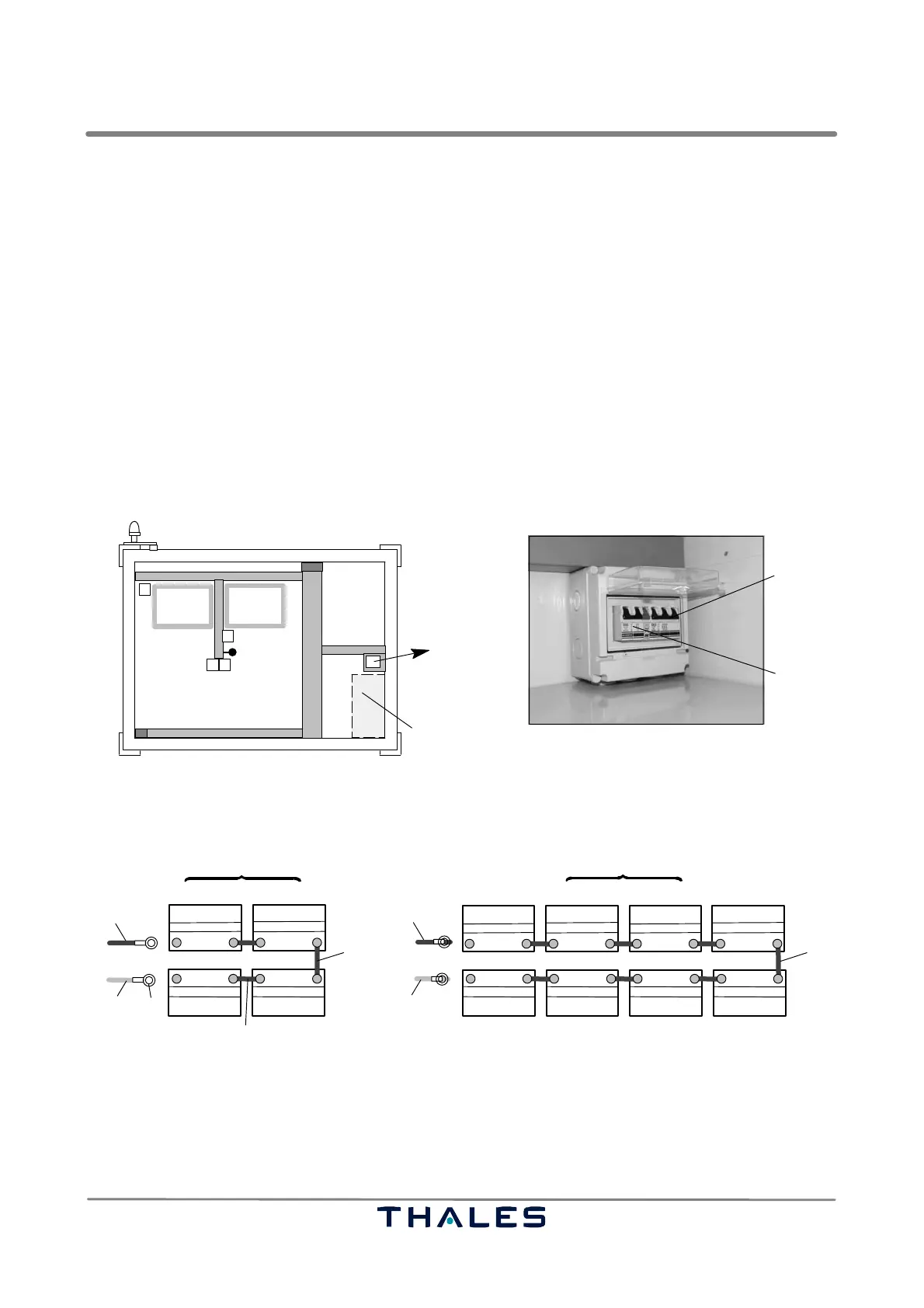
2.3.3.3 Installing sulphuric acid Batteries for Emergency Power Supply
NOTE: Take out block batteries from the transport case just before the first setup activities have
to be performed.
− Switch off battery circuit breaker F20 and F21 (down position, 2−10/2,1).
− Put the battery set G1 to Gn in the battery compartment (2−6/10) and connect depending on type
of battery set as shown in Fig. 2−11.
− Connect all block connections (2−11/4).
− Connect cable terminal of the positive line (16 mm
2
, red, 2−11/1) to the positive pole of the battery.
− Connect cable terminal of the negative line (16 mm
2
, blue, 2−11/2) to the negative pole of the bat-
tery.
− Connect 3 monitoring and measurement lines (1,5 mm
2
) to battery "+" , "−", and half voltage point
(middle of battery set).
− Fasten all screws of the battery terminals (torque moment 15 Nm).
1 Battery circuit breaker fuse F21
2 Battery circuit breaker fuse F20
Shelter wall, right, inner view
1
2
Battery compartment
Fig. 2−10 Battery fuse box
1 Positive line (red) 4 Block connection
2 Negative line (blue) 5 Emergency battery 48 V(4x 12 V); capacity depends on type: 54, 72, 90 or 108 Ah
3 Cable terminal 6 Emergency battery 48 V(8x 6 V); capacity depends on type: 128 or 192 Ah
1
−+ −+
−+−+
G1 G2
G3
G4
4
−+−+
G1 G2
−+−+
G3 G4
−+ −+
G7
G8
−+ −+
G5
G6
1
4
5
2
2
4
3
6
*)
*)
*) half voltage
Fig. 2−11 Emergency battery set