LLZ 421
Operation and Maintenance Installation
ILS 420
2−21Ed. 01.04
SOAC
2.4.5.4 Connection of detected monitoring Signals from Antenna (option)
See Figs. 2−19, 2−20, 2−21.
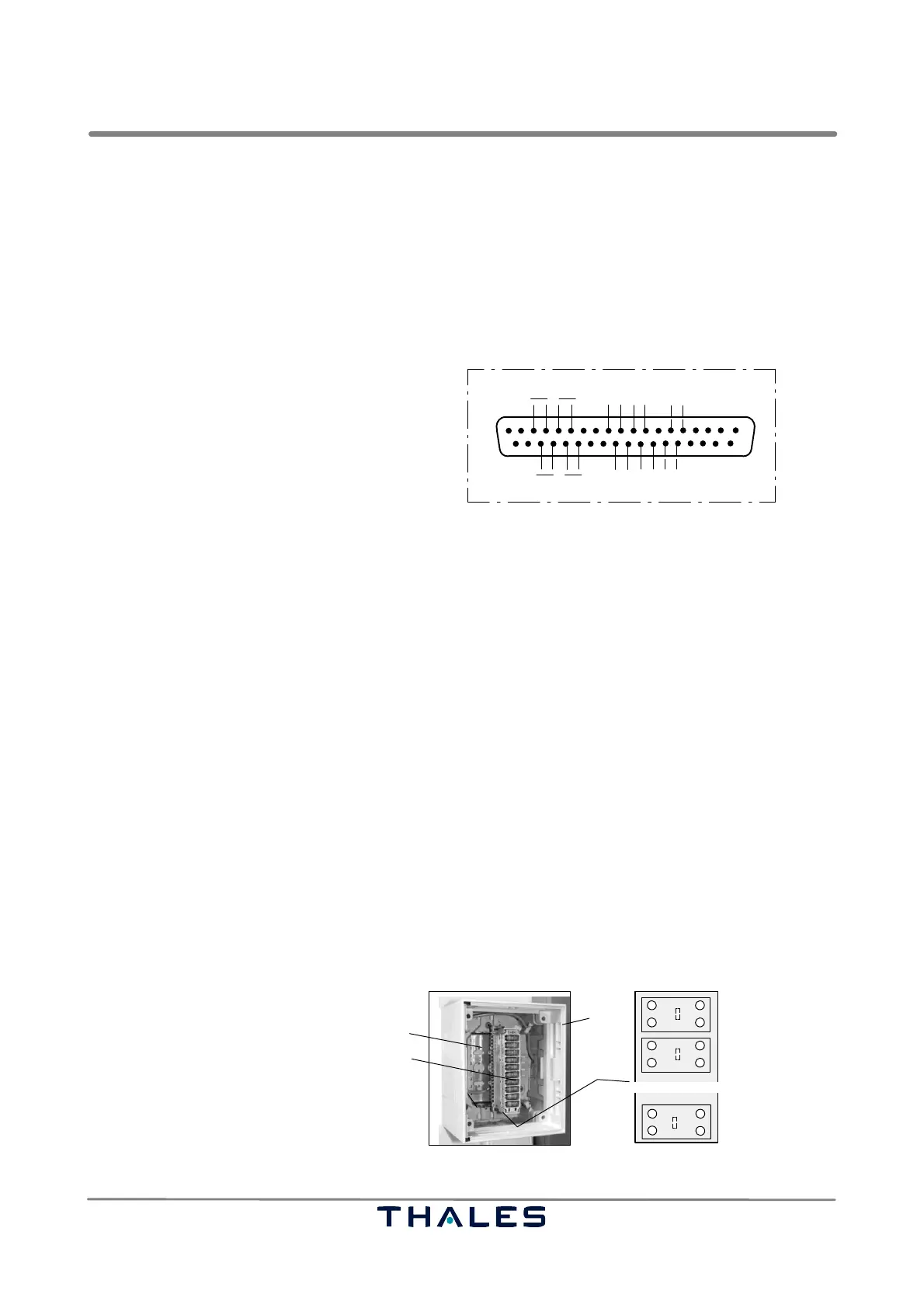
Connector J10 is used to interconnect optionally antenna sensor signals (e.g. Farfield Monitor) which
are located outside the cabinet. A multi conductor cable (e.g. 10 pairs) supplies the detector signals
first to the AF distribution box (Abb. 2−20) in the shelter. The recommended assignment of terminals
is shown in Fig. 2−21. From the AF distribution box the multi conductor cable is fed to the transmitter
rack. Connect the cable to a SubD connector 37pin, male. Plug the connector to connector J10 (ENV.
SENSORS, DME, DETECTOR IN) on top of the cabinet. Fig. 2−19 shows the pin assignment.
20
19
37
View on connector soldering pins
1
c)
a)
c)
J10
J10: Detector signals (FFM1,2; cable fault signal A, B)
PIN SIGNAL
a) 3,22 +24V1
4,23 GND
b) 5,24 +24V2
6,25 GND
c) 10 CABLE FAULT A (spare)
29 CABLE FAULT B (spare)
d) 11 DET5A FF1
30 DET5B FF1
e) 12 DET6A FF2
31 DET6B FF2
e)
f) g)a)
d)
d) e)
f) g)
b)
a)
f) 32 DME INTERLOCK A
14 DME INTERLOCK B
g) 33 DME KEY A
15 DME KEY B
*) 9,28 optional ext. voice input
*
*
NOTE: The NF signal level of the integrated farfield monitor at the input J10 should be approx. 1.8 V (max. < 2 V).
Fig. 2−19 Assignment of connecting detector signals at J10 on top
2.4.5.5 AF Distribution Box
See Figs. 2−20, 2−21.
The AF distribution box is the entry point for AF signal lines, which are fed from external to the shelter.
The recommended assignment of the 20 connection terminals (10 pairs) is shown in Fig. 2−21. Each
line is protected by overvoltage arrester elements. As an option a second terminal bar can be as-
sembled.
− Remove the plug−in module with arrester elements.
− Connect the skinned wire of the signal cable to the respective terminal of the terminal bar (use spe-
cial tool of manufacturer Krone).
− Finally insert the plug−in module with arrester elements.
NOTE: Connect the screening of the data or AF signal cable one sided to ground: either on the
AF distribution box or on the airport side. Use the recommended assignment of terminals.
1 AF−distribution
2 Terminal bar below plug−in modules
3 Plug−in module with overvoltage arrester elements
4 Terminal base (reserve)
1
2
4
1a
1b
1a
1b
2a
2b
2a
2b
10b
10a
10b
10a
3
Fig. 2−20 Standard shelter, AF distribution box inside (standard)