LLZ 421
Operation and Maintenance Installation
ILS 420
2−31Ed. 01.10
SOAC
2.5 GROUNDING
2.5.1 General
The type of grounding implemented is dependent on the local terrain. Consequently it is only possible
to provide general guidelines here. Grounding conductors or rods are metallic elements of a particular
form which are either driven into the ground or laid in the ground so as to cover a relatively large area.
NOTE: All connections in the ground must be welded and protected against corrosion.
The ground resistance required for a navigation installation can be given as
5 . This resistance
can only be measured precisely with the aid of special ground resistance measuring equipment. The
exact measuring procedure is described in the operating instructions for these devices. Universally
valid instructions are given in Section 2.5.6. Sufficient grounding can generally be obtained if the
installation suggestions described below and the terrain conditions are paid attention to. When esti-
mating the ground resistance the length and extent of the network laid are the crucial points, not the
cross−sectional area of the conductors. Favorable resistance conditions are provided by arable land
and loamy ground (ground resistivity 100 per meter). The data specified below applies to these
conditions. With other types of terrain the factors below must be taken into consideration (increase
in the resistance with respect to the basic values stated).
Moist sandy soil 2x
Dry sandy soil 5 to 10x
Gravel or stones up to 30x
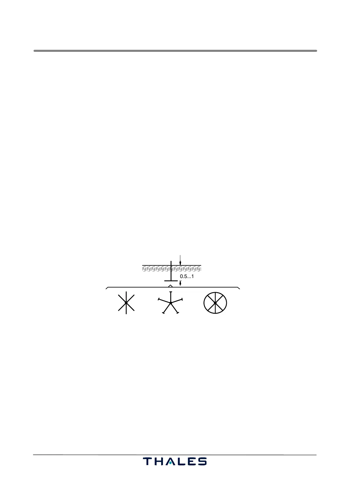
If the ground is not chemically neutral, e.g. if it is salty, it may be necessary to coat all metal parts laid
in the ground with lead or to use a sufficiently non−corrosive steel (e.g. V2A). The different types are
shown in Fig. 2−27.
0.5...1 m
Radial ground Ground rod or plate Interlinked ground
Fig. 2−27 Different types of ground conductor configuration
2.5.2 Strip or Mesh Ground Conductors
Strip ground conductors take the form of a strip, round material or cable laid in the ground at a depth
of 0.5...1 m so as to cover a relatively large area. Materials:
Steel strip (hot galvanized) 100 mm
@, min. thickness 3 mm
Copper strip 50 mm
@, min. thickness 2 mm
Copper cable (not finely−stranded) 135 mm
@
The network should be laid as symmetrical to the LLZ or GP station as possible. The necessary length
and extension when laid in a straight line, should be estimated from the basic data below.
Strip length Ground resistance
25 m 10
50 m 5
100 m 3