LLZ 421
Operation and Maintenance Alignment Procedure LLZ−2F (LPD)
ILS 420
8−13Ed. 07.08
SOAC
8.4 SETTING THE MONITORS
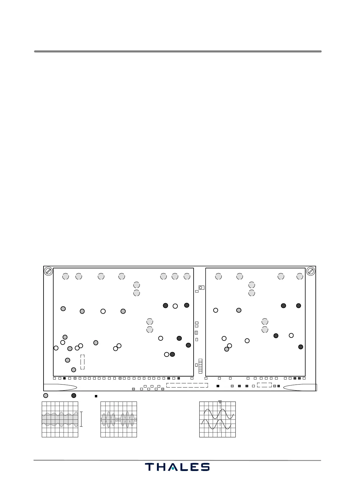
See Fig. 8−2, 8−3, 8−4.
The Stby and On−Air Combiner (SOAC) unit processes the input monitoring signals of the aerial and
standby transmitter. It is supposed that the SOAC is factory pre−aligned. However, on site field adjust-
ment is necessary. For correct operation the 7 monitor channels have to be set in a certain manner:
1) The RF input signal of each path on the SOAC is down converted to an 8 kHz IF signal. This signal
has to be adjusted to an output signal of approx. 3.6 Vpp. The 8 kHz IF amplitudes are measured
with an oscilloscope at the corresponding test points. Coarse adjustment of the input level is per-
formed with attenuators which are inserted or bypassed with the corresponding jumpers (see sec-
tion 6.6.5), if need be. Figs. 8−3, 8−4 show the signal path, the potentiometers and the corre-
sponding testpoints of each channel on the SOAC. Recommendation: Use a special alignment
screw driver with immersed blade for the potentiometers.
If need be, e.g. phase cannot be adjusted, insert phase adapters or cables to the concerned input.
2) When the signals in the field are set correctly, the input signal to the monitors, the measured values,
represent nominal values and have to be entered in the corresponding data window (Open dialog
’Monitor1−Nominal Values’ or open dialog ’Monitor2−Nominal Values’).
3) The monitor has to be supplied with a calibration signal (CRS CSB) adjusted to 40 % SDM and
0 % DDM. This signal is used to calibrate the monitor channel. Set ’ILS ident keying’ to ’Continu-
ous’ (Remark: It must not be set to 0 %). With a known SDM and DDM, the monitor is able to calcu-
late the third unknown parameter: the RF−LEVEL.
4) Finally the original signal is supplied to the monitor. With this signal the monitor has to be normal-
ized. The automatic normalization procedure runs only if the actual DDM and SDM values do not
vary to much from the Nominal Values !
R105
R90 R62 R43
R2 R511
R25
R382
R372
R383
R189
R185
R386
R379
R377
R166
R150
R146
R123 R136
R133
R499
R524
R275
R286
R327
R345
R343
R353
R240 R217
R318
R305
R312
J10 J9 J8 J7
J4
J1
J3
J5
J2 J47 J6 J17 J18 J16 J12
J13
J15
J14
J11
J20
J21
R485
CLR Stby
CSB
CLR Stby
SBO
CLR Width(1)
CRS Stby
SBO
CRS StbyCRS SBONearfield
CSB
CRS CSB
TP65
TP62
TP59
TP66
TP63
TP60
TP64
TP61
TP15
TP18
TP17
TP14
TP16
TP13
TP11
TP10
TP12
TP7
TP9
TP6
TP8
TP2
TP3
TP1
TP4
TP5
TP56
TP74 TP76 TP72
TP41 TP77 TP75 TP73 TP51
TP57 TP58 TP55 TP29 TP26
TP24
TP27
TP25
TP31 TP21
TP22
TP23
TP19
TP20
TP53 TP47 TP49 TP37 TP39 TP34TP30
TP67
TP69
TP70
TP68
TP71
GND
GND
JP41
JP43
12
aerial standby
CRS Wi
CRS Po
Stby CRS Pos Stby CRS Wi Stby CLR Wi
CLR Wi
NFM Po
GND
Level adjustment; one channel, Phase adjustment, using delay trigger facility
Signal A (e.g. TP1 CSB)
Signal B (e.g. TP5 SBO)
trigger ext. with CSB signal
J19
e.g. TP11 at LGA
3.6 Vpp
CSB SBO
approx.
Fig. 8−2 Adjustment controls and test points of SOAC