LLZ 421
Operation and Maintenance Installation
ILS 420
2−11Ed. 01.04
SOAC
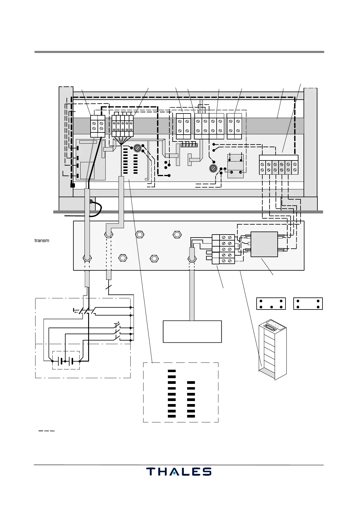
L1 L2 L3NPE
rear side of transmitter rack, BP−PS
BAT BAT
+B −B
5
bottom plate with
cable glands
mains connection box
shelter
230 VAC
transmitter rack
FPE
(european version only)
C−barbattery terminal
measuring line
connector
DME
terminal
RL
terminal
mains terminal
mains terminal
mains filter
emergency battery battery box
48 V
+
−
fuse box
BFUSE
BFUSE
BAT2
BAT1
BAT0
50 A
0.2 A
DC
F20
F21
1
2
3
4
24
23
21 FF0
−N+N
PE
NL1L2L3
L3
L2
N
L1
PE
L1
N
L2
L3
L3
L2
L1 N
L2
L3
NL1
PE
connectors position:
IN
OUT
LVS
X10
X8
X9
X4
DCC−5
X2
X3
−A+A
F4
F5
REL1
SP26
SP10
TX1
to S1 (TX1)
to S2 (TX2)
TX2
from S2
from S1
DME+
−D+D −R+R
DME−
DC to TX
P54 LG−A
Ubat −
P15 TX2
P5 TX2
N15 TX2
GND TX1_1
GND TX1_2
GND TX2_2
GND TX2_1
P24 TX2
P15 INTFC
P15 TX1
P5 INTFC
P5 TX1
N15 TX1
N15 INTFC
P24 TX1
Assignment DC to TX1/2
to REL1
to LCP
to GND
from LVS
54+
factory wired
54+
Ground bolt
N_1
L2_1
not used
not used
to Shelter ground
(regard NOTE)
NOTE:
As special option a 2 phase mains connection
(e.g. L1, L2) may be established for individual
supply of AC/DC converter. In this case the
standard bridge between L1 and L2 at the
mains terminal has to be removed.
Fig. 2−13 Connections at the backpanel BP−PS, C−bar and bottom plate