LLZ 421
Installation Operation and Maintenance
ILS 420
2−6 Ed. 01.04SOAC
2.3.3 Electrical Installation
2.3.3.1 General
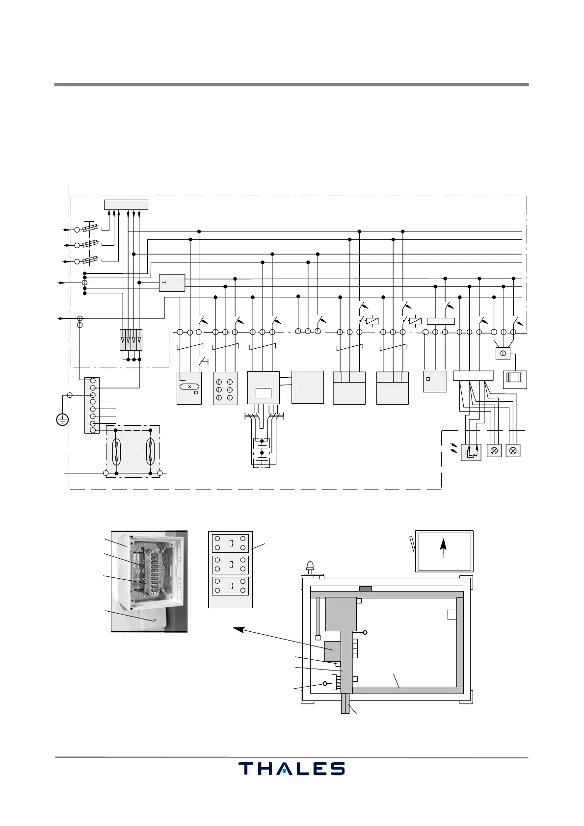
Fig. 2−7 shows an example wiring diagram of a standard electrical shelter installation (typical). The
final installation depends on customer requirements.
* Example diagram for Mains Supply with 3 Phases, N and PE
20 protected wires
BCPS
DME
if available
Spare
A/C1
L1
L2
L3
N
PE
Signal lines
Station Ground
NF 600 OHM
Overvoltage
Protection
Line Terminal Box (AF−distribution)
Inside Light Socket outlets
Air−Conditioner
Single Phase "Option"
F4 F3 F1
F2
F5 F7
Main Distribution Panel
Earth Collector Bar
Main Fuse
Residual
Current Breaker
BCPS
TX Rack
DME
etc.
*
Wiring Diagram of electrical Installation
40
0.03
TX
switch
option box
. . . .
. . . .
. . . .
B18A
B10A C20A
F20 (2x K50A)
F21 (2x G0.2A)
C20A
A/C2
F6
C20AC20A
1234 56789
F8 F9
B2A
B10A
B10A
10
change o.
Te m p .
Sensor
set to
36 °C
θ
junction box
heater
. .
obstruction lightstwilight
switch 1
optional
optional
Emergency battery
48 V
+
−
90 V/Type F
+
−
−
DME
48 V
FI1
2
(or ten pairs)
I>
Fig. 2−7 Standard shelter, electrical installation LLZ (example)
1 AF−distribution
2 Connector base
3 Plug−in module with overvoltage arrester elements
4 Phone connector socket
5 3 cell cable duct
6 Earthing main connector
7 Protective tube for data cable
8 Cable duct
9 Connector base, plug−in module removed (Pos. 3)
left shelter wall, inner view
1
2
7
3
5
6
4
8
1a
1b
1a
1b
2a
2b
2a
2b
3a
3b
3a
3b
9
4
Fig. 2−8 AF−distribution box