LLZ 421
Operation and Maintenance Operation
ILS 420
3−5Ed. 01.07
SOAC
Ê
Ê
Ê
Ê
Ê
Ê
Ê
Ê
Ê
Ê
Ê
Ê
Ê
Ê
Ê
Ê
Ê
Ê
Ê
Ê
Ê
Ê
Ê
Ê
Ê
Ê
Ê
Ê
Ê
Ê
Ê
Ê
Ê
Ê
Ê
Ê
Ê
Ê
Ê
Ê
Ê
Ê
Ê
Ê
Ê
Ê
Ê
Ê
Ê
Ê
Ê
Ê
Ê
Ê
Ê
Ê
Ê
Ê
Ê
Ê
Ê
Ê
Ê
Ê
Ê
Ê
LCP
ACC 54
ACC 54
BP MODPABP DigitalBP−PS
TX1 TX2
DCC−MV /1
DCC−MV /2
SYN 1
VAM*
Interface INTFC
LG−A 2
SYN 2
LG−M 1
LG−M 2
MOD/PA 2/1
MOD/PA 1/1
MOD/PA 1/2
MOD/PA 2/2
Modem*
Modem*
ECU
LG−A 1
Stby and On−air Combiner
(includes combining network for GP, not used in LLZ)
J20 J21
front side
* optional** 2F only
LG−A/LG−M
Load/boot
Board reset
CPU_Normal
Audio On
LC−CPU
CPU live lamp, green
Reset switch
Key and test jack
PM1 test condition
M1 modem operable
M5* comm. line subsystem
and RCSE operable
Answ. modem occupies line
S1 DEE operable
FKS8 connector
* LGM28.8D1 opt.5
LGM
PM1 Answ.
M1 (M5*) S1
ACC
Converter on/off
test jack Uout
+54 V available (LED)
R32, fine adjustment battery
charging voltage
DC/DC ok (LED)
SYN
VCO’s off (LED)
ECU
Executive ON
Bypass On
Exec. Alarm Monitor 1
Exec. Alarm Monitor 2
Standby On
Standby Bypass On
Standy Alarm Monitor 1
Standby Alarm Monitor 2
Field Bypass On
Field Alarm Monitor 1
Field Alarm Monitor 2
Equipment 1 Executive
3 RD off
Integrity Fail
Switch Fail
Equipment Select
Reset Board
Lamp test
LCD brightnessR1
CW RFout CLR
CW RFout CRS
MOD/PA 2/1
MOD/PA 1/1
MOD/PA 1/2
MOD/PA 2/2
CLR CSB/SBO
CRS CSB/SBO
CRS CSB/SBO
CLR CSB/SBO
−
CRS CSB/SBO
CRS CSB/SBO
−
TX1
TX2
2F 1F
2F 1F
DCC−MV
Main switch DC TX1, TX2 on/off
HD LED
BP−PS rear
Fuse
F4F5
Remark:
The RFcw connections of CRS and CLR frequency
from J7 or J6 at the Synthesizer to the CRS and
CLR MODPA may be interchanged. But in one cab-
inet both TX must be connected the same.
VAM−ILS*
Line/Mic
Mic
Line
Sign.
Mic in
out
voice
Hex Switch
key tone (ident)
INTFC
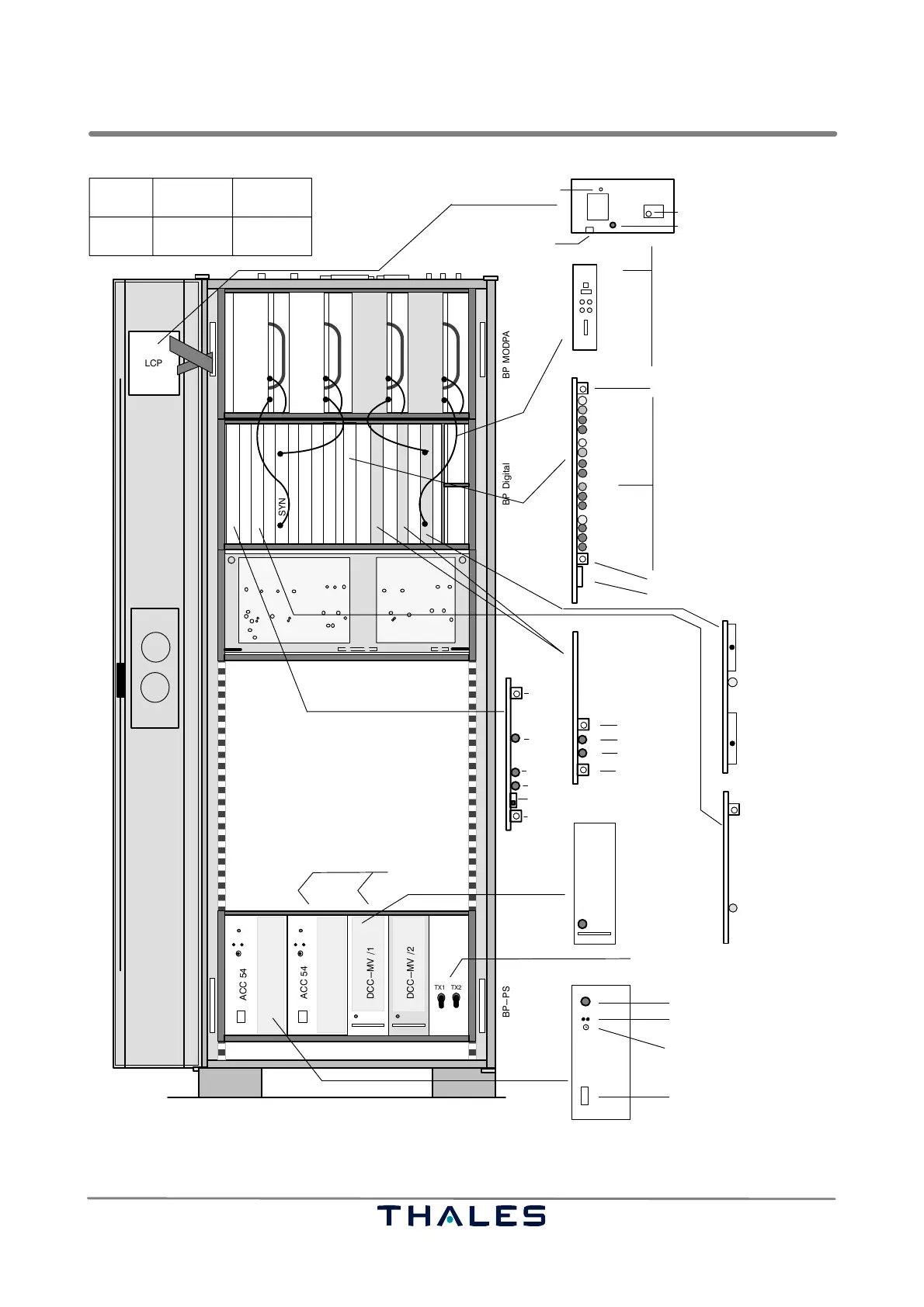
Fig. 3−2 Push buttons and indications on the subassemblies inside the rack
Ed. 01.10