LLZ 421
Operation and Maintenance Operation
ILS 420
3−7Ed. 01.07
SOAC
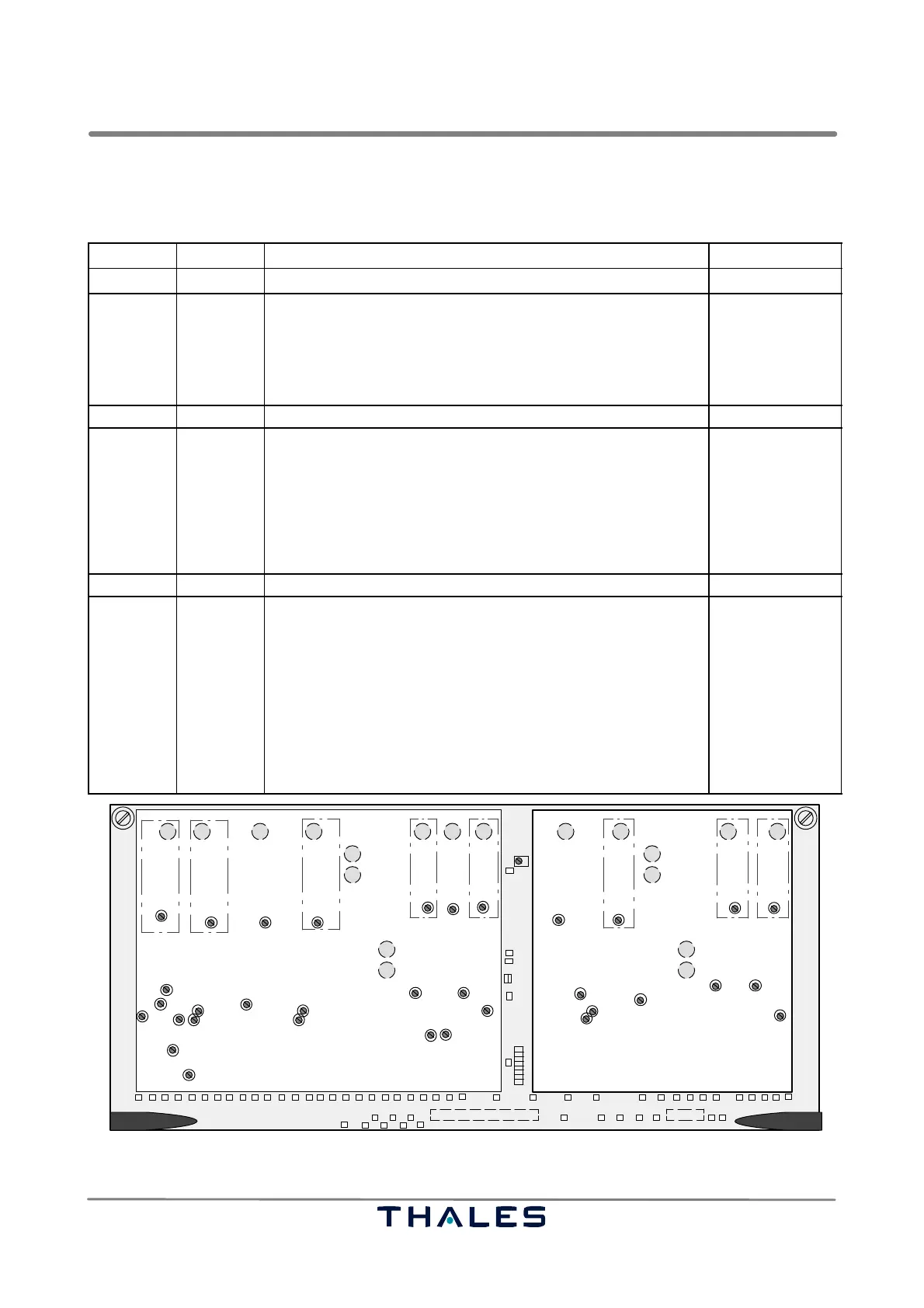
3.3.1 Controls and Test Points at the Stby and On−Air Combiner (SOAC)
The following table lists the control elements (potentiometer) and test points used for first setup.
Control Test point Function Remarks
aerial RF in Gain adjustment input
R105
R90
R62
R43
R275
R286
TP18,TP41
TP16
TP12
TP8
TP24
TP71
IF gain adjust of nearfield monitor input signal (NFM)
IF gain adjust of LLZ CRS Posn. input signal (CSB*)
not with LLZ
IF gain adjust of LLZ CRS Width (SBO*) input signal
IF gain adjust of LLZ CLR Width 2 input signal
IF gain adjust of LLZ CLR Width 1 input signal
−
−
−
−
not used
−
aerial IF path phase adjustment
R166
R353
R345
R150,146
R189,185
TP13
TP11
TP25
TP27
TP26
TP6,TP9
TP14,TP17
Phase adjust of LLZ CRS Width signal; only with LPD antenna
used for mid set of R166 resistance range
Phase adjust of LLZ CLR Width (1) signal; no need for LLZ
Phase adjust of LLZ CLR Width (1) signal; no need for LLZ
used for mid set of R345 resistance range; not for 1F
path not used in LLZ
path not used in LLZ
w. LPD antenna
factory aligned
not applicable
not applicable
factory aligned
−
−
aerial IF path Level adjustment output
R377
R379
R383
R382
R327
R343
R386
R372
TP51
TP63
TP66
TP64
TP53
TP37
TP39
TP65
TP62
IF level sum adjust of LLZ CRS Posn. output signal
IF level adjust of CSB for CRS Width signal path (CSB+SBO)
IF level adjust of LLZ CRS Width signal path
IF level adjust of CSB for CRS Width signal path (CSB+SBO)
IF level adjust of LLZ CRS Width output signal
IF level sum adjust of LLZ CRS Width output signal
LLZ−2F only: IF level adjust of CLR Width (2) output signal
LLZ−2F only: IF level adjust of CLR Width (1) output signal
not used in LLZ
not used in LLZ
−
w. LPD antenna
w. Dip./Reflect.
w. LPD antenna
w. Dip./Reflect.
w. LPD antenna
not used
−
−
J10 J9 J8 J7
J4
J1
J3
J5
J2 J47 J6 J17 J18 J16 J12
J13
J15
J14
J11
J20
J21
R485
TP65 TP59 TP63 TP64 TP15 TP17 TP16 TP11 TP12 TP9 TP8 TP3 TP4 TP56
TP74 TP76 TP72
TP41 TP77 TP75 TP73 TP51
TP57 TP58 TP55 TP29 TP26 TP27 TP31 TP21 TP23 TP20
TP53 TP47 TP49 TP37 TP39 TP34TP30
TP67
TP69
TP70
TP68
TP71
GND
GND
JP41
JP43
12
R275
R286
R327
R345
R343
R353
R240 R217
R318 R305
R312
TP24 TP25 TP22 TP19
R133
R105
R90 R62 R43
R2 R511
R25
R382
R372
R383
R189
R185
R386
R379
R377
R166
R150
R146
R123 R136
R499
R524
TP62 TP66 TP60 TP61 TP18 TP14 TP13 TP10 TP7 TP6 TP2 TP1 TP5
NFM CRS Posn.
CRS Width
CRS CSB
Stby
CRS SBO
Stby
CRS Width (1)
CLR SBO
Stby
CLR CSB
Stby
RFcwCLR TX1
RFcwCRS TX1
RFcwCRS TX2RFcwCLR TX2
* LLZ with LPD−antenna
CRS CSB* CRS SBO*
Fig. 3−3 Stby and On−Air Combiner (SOAC), front view, controls and test points