LLZ 421
Operation and Maintenance Alignment Procedure LLZ−1F (Dip./Refl.)
ILS 420
4−5Ed. 01.10
SOAC
4.2 FIRST SWITCHING ON
4.2.1 Status of the System
− Mains OFF (mains distribution unit, shelter)
− Battery fuse switches open (used for emergency battery, battery fuse box, shelter)
− Power switches on BCPS (ACC modules, transmitter cabinet) in position OFF (0)
− DC−switches TX1 and TX2 on subrack PS (transmitter cabinet) in position OFF
CAUTION
All CSB and SBO RF outputs must either be terminated with a dummy load or connected
to antenna. Otherwise the transmitter may be damaged when switching on the equip-
ment.
4.2.1.1 Special Jumper Settings before Start Up
Individual jumpers have to be set before the first switching on. The location of jumpers is shown in
Part 2, Localizer Manual. Perform the following settings:
− LCP: Set jumper X36 (enabling backup battery for RTC).
− SOAC: Check that jumper J1 and J6 are set to 1−3, 2−4 (1F installation only).
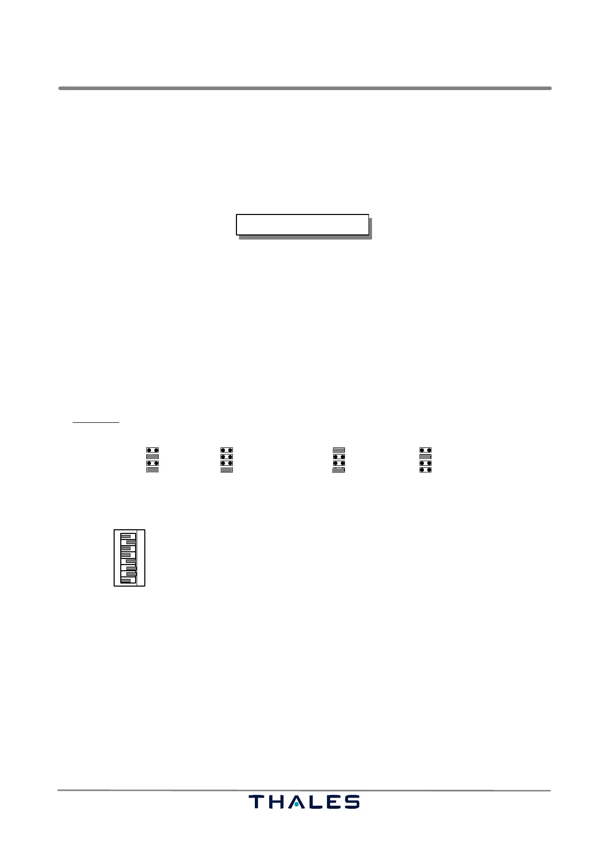
− SYN: Set jumpers J1 to J4 according to the selected operating frequency:
J1: 300 or 100 and tenth J2: units
J3: one tenth J4: one hundreds and thousandths
Example:
The LLZ frequency is selected to 111.95 MHz. Perform following settings:
J1
J2 J3 J4
300
100
20
10
8.0
4.0
1.0
0.8
0.4
0.2
0.1
.075
.050
.025
.000
2.0
100+10 1= 1.0
.9=.8+.1
.05 = 111.95
− ECU: Set switch SW1 according to selected station configuration and jumpers J6, J7, if specific
DME operation is required. This setting must correspond to software configuration data. Standard
setting of SW1 is:
Transmitter 1 is main
Interlock on (control follows interlock bit)
Monitor AND configuration enabled
Hot Standby set
1
2
3
4
5 open
closed
open
closed
closed
6
7
Closed if farfield monitor available (FFM, LLZ)
open Closed if field monitor available and executive
open
Standard setting:
Station remains operable
23 45 6 781
open
SW1
TX1 is main
Stand alone
AND
Hot stby
Enable
Exe field
Shut down 30 s
DME independent
TX2 is main
Interlock
OR (Monitorkonfiguration)
Cold stby
Disable field monitoring
No Exe Field
Remain
DME Interlock
closed No DME8
4.2.2 Switch On
a) Connect PC serial interface connector (e.g. COM1) to RS232 connector ’Local PC’ on top of the
cabinet with a ’zero modem cable’ (rx/tx crossed).
NOTE: If the PC has no serial interface, use adapter USB to Serial. Refer to TM ADRACS, chapter 1.
b) Switch on mains and set power switches of BCPS (ACC modules, cabinet) to position ON.
c) Close battery fuse switches (battery fuse box, inside shelter).
NOTE: Matching the charging voltage of BCPS modules to environmental conditions: Refer to 6.3.3.
d) Set DC switches TX1 and TX2 on subrack PS (transmitter cabinet) to on.
e) Switch to local control with the key−lock switch on the Local Control Panel(LCP).
REMARK: ILS LLZ−2F with Out of Phase Clearance: The correspondent measurements and result-
ing settings are made during flight check via software program. The Out of Phase Clea-
rance setting is only used if critical DDM−distortions exist (signal out of specification).