LLZ 421
Operation and Maintenance Operation
ILS 420
3−17Ed. 01.10
SOAC
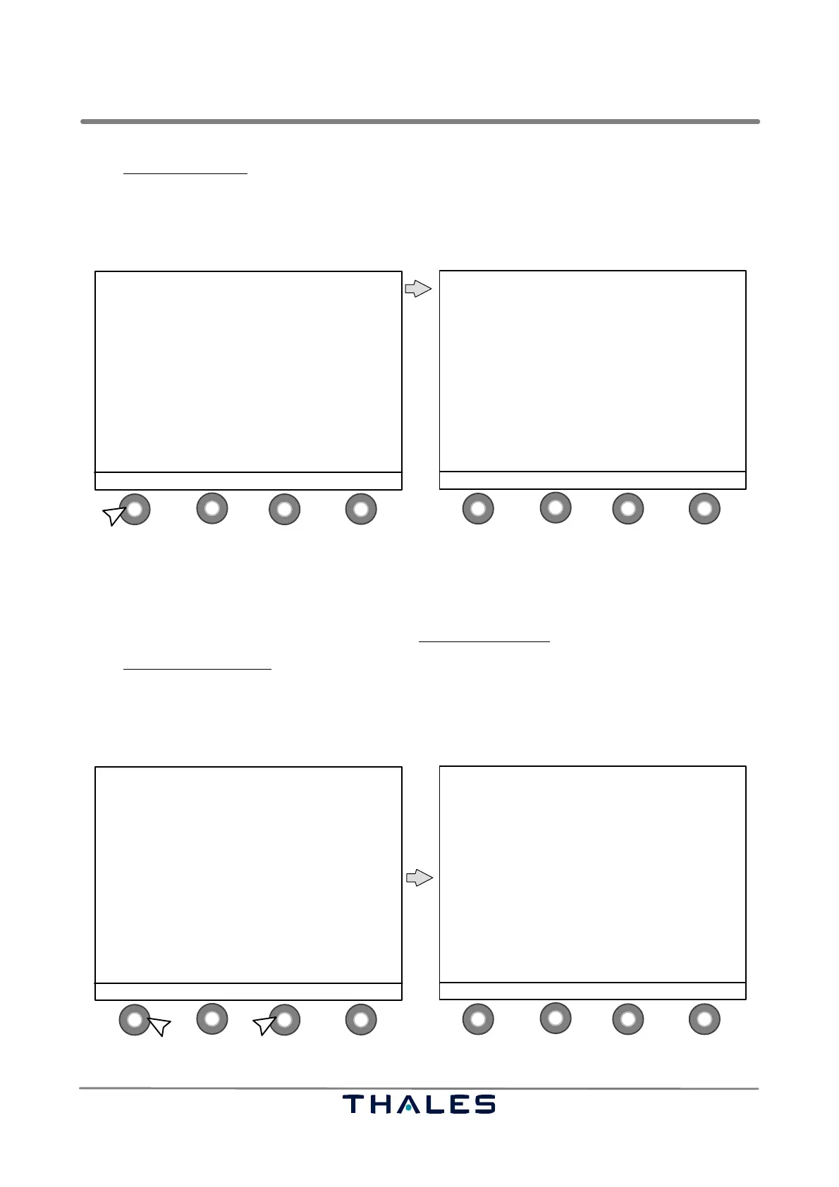
In the Menu List window the following button definitions are used:
− S1 ENTER to enter/confirm selected item in the Menu List
−S2 ↑ to select menu item, upwards, selected item is pointed with >
−S3 ↓ to select menu item, downwards, selected item is pointed with >
− S4 STATUS to return to the Status window (see Fig. 3−6)
1
4
2
3
1
4
2
3
ILS 420 LLZ ’LLZ−420T’ 110.10MHz
−−−−−−−−−−−−−−−−−−−−−−−−−−−−−−−−−−−−−−−−
TX 1: ON TX 2: ON
STANDBY MAIN
LOAD AERIAL
146 hrs. 145 hrs.
Monitor: −−1−− −−2−−
Executive: NORMAL NORMAL
Farfield: NORMAL NORMAL
Standby: NORMAL NORMAL
RWY: ON
MENU MONITOR ALERTS CONTROL
MENU LIST
−−−−−−−−−−−
> SHOW ALERTS
CONTROL
MONITOR QUICK ACCESS
MONITOR EXEC & FIELD all parameters
MONITOR STANDBY all parameters
POWER SUPPLIES
WAVEFORM DATA / FLIGHT CHECK
POWER AMPLIFIER DATA (CRS and CLR)
MTBO
CONFIGURATION DATA
ENTER ↑ SELECT ↓ STATUS
**
*
* depends on configuration *
control buttons (S)
* CONTROL and FLIGHT CHECK not for ’REMOTE’
**
Fig. 3−15 MENU select and MENU LIST window (example)
The windows shown after selecting STATUS, SHOW ALERTS, CONTROL and MONITOR QUICK AC-
CESS Menu List items are already described and shown in previous Figs. 3−6 to 3−14.
Following Figs. 3−16 to 3−20 show/describe the Menu List windows
after selecting the other items:
In the Monitor Exec. & Field
window the following button definitions are used:
− S1 MENU to return to the Menu List window
−S2 ↑ to scroll parameters upwards
−S3 ↓ to scroll parameters downwards
− S4 STBY−MON to go to Monitor Standby window (see Fig. 3−17)
1
4
2
3
1
4
2
3
MENU LIST
−−−−−−−−−−−
SHOW ALERTS
CONTROL
MONITOR QUICK ACCESS
> MONITOR EXEC & FIELD all parameters
MONITOR STANDBY all parameters
POWER SUPPLIES
WAVEFORM DATA / FLIGHT CHECK
POWER AMPLIFIER DATA (CRS and CLR)
MTBO
CONFIGURATION DATA
ENTER ↑ SELECT ↓ STATUS
AERIAL: TX2 / ON AERIAL−ALL
1 MONITOR 2
CRS POS RF % 100.2 100.3
DDM % 0.0 0.0
SDM % 39.0 39.1
IDENT % 8.0 8.0
CRS WDTH RF % 100.9 100.8
DDM % 15.5 15.5
SDM % 38.9 39.0
CLR WDTH RF % 100.0 100.2
DDM % 23.7 23.8
SDM % 39.9 39.9
MENU ↑ SCROLL ↓ STBY−MON
1.
2.
control buttons (S)
Fig. 3−16 MONITOR EXEC. & FIELD select and Monitor Exec. & Field window (example)