LLZ 421
Alignment Procedure LLZ−1F (LPD) Operation and Maintenance
ILS 420
7−12 Ed. 07.08SOAC
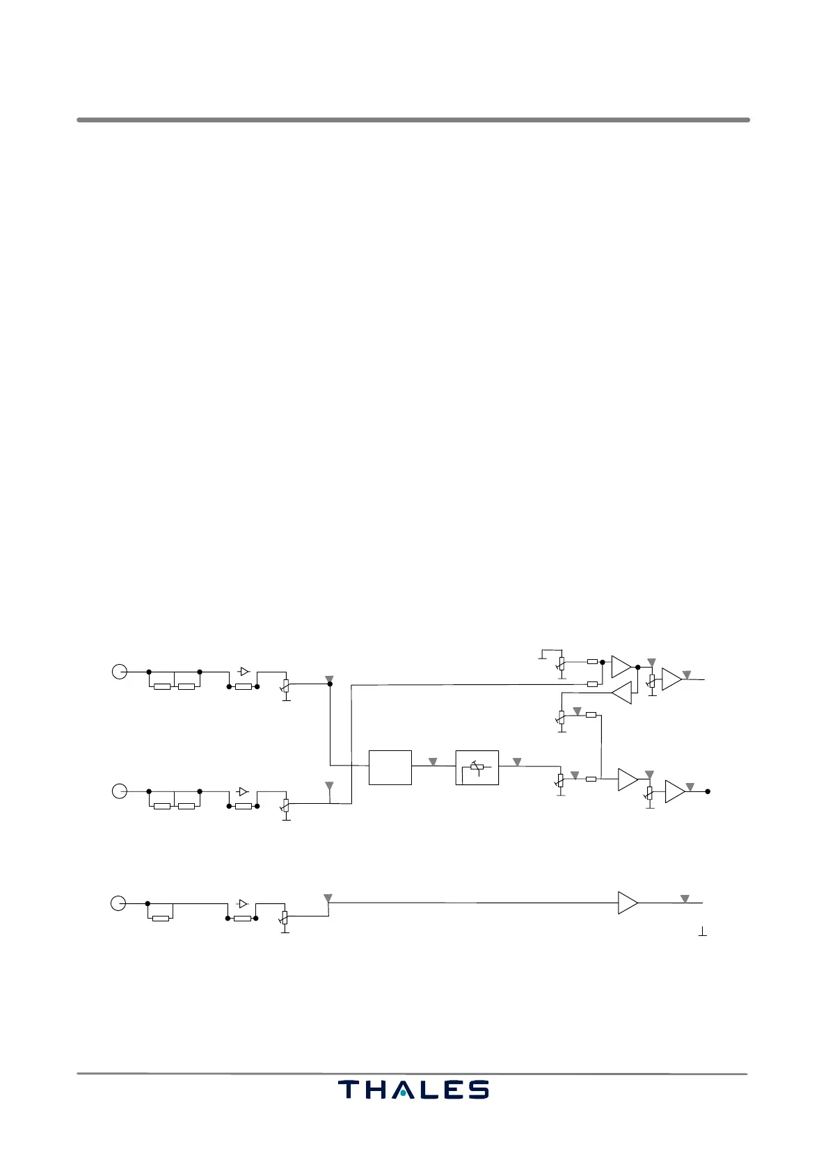
7.4.1 Adjustment Procedure of Aerial Channels
See Fig. 4−8, 7−2, 7−3, 7−5.
NOTE: The signal path used within the SOAC is set to 11−12 on J19 of SOAC.
(used for LPD antenna with CU part no. 120631−0001; alternative setting is 9−10, use procedure and path of section 4.4.1)
Do not use +15 dB amplifiers in the SOAC input path. The signal must not be overdrived.
7.4.1.1 CRS Posn. Channel (Input connector J9)
− Connect oscilloscope to TP51 and TP59 (GND). Measure output level. Adjust IF gain to achieve
approx. 3.6 Vpp output: perform first coarse alignment removing or inserting attenuators with
JP16,17 or J18,19; perform fine adjustment with R90 and finally R377.
7.4.1.2 CRS Width Channel (Input connector J7)
− Connect oscilloscope to TP63 and TP59 (GND). CRS CSB path is set; adjust with R379 to achieve
1.5 Vpp at TP63. Connect oscilloscope to TP13: Perform first coarse alignment of CRS SBO path
removing or inserting attenuators with JP7,8 or JP9,10 and fine adjustment with R43 to achieve
0.16 Vpp. Check relative CSB − SBO phase with oscilloscope, measure between TP63 (CSB) and
TP13 (SBO), see Figs. 4−8, 7−3, 7−5. Adjust with R166 to 180°. If need be readjust R379 for CSB
component level. CRS Width DDM is defined by the SBO/CSB ratio set with mainly R383 and R379.
Finally adjust output level with R382 to approx. 3.6 Vpp at TP53.
7.4.1.3 NFM Channel (Input connector J10). Refer also to 7.4.3.3.
− Connect oscilloscope to TP41 and TP59 (GND). Measure output level.
Adjust IF gain to achieve approx. 3.6 Vpp output: perform first coarse alignment removing or insert-
ing attenuators with JP22 or J23,24; perform fine adjustment with R105.
IF gain set
R43
CRS SBO in
J7
R377
out
CRS Posn
TP8
R372
JP7
JP9,10
in
TP51
input attenuation
−5 dB
Output level adjust
−10 dB −10 dB
3.6 V
TP62
JP8
setting depends on local condition
R382
CRS Width
TP53
Output level adjust
TP66
TP63
R379
out
3.6 V
IF gain set
R90
CRS CSB in
J9
TP16
JP16
JP18,19
in
input attenuation
−5 dB−10 dB −10 dB
JP17
TP64
R383
TP13
TP10
Phase adjust
fixed
phase
R166
nom. 90° lag
TP11
preset to mid*
factory field
preset to mid*
not used
preset to mid*
preset to mid*
setting depends on local conditions
−/+
+15 dB
+15 dB
IF gain set
R105
NFM Posn.
J10
out
NFM Posn.
TP18
JP22
JP23,24
in
TP41
input attenuation
−5 dB
Output level
−10 dB
3.6 Vpp
set ting depends on local conditions
* initial setting
TP59, TP30 GND
+15 dB
ca. 0.6Vpp
ca. 3.2 Vpp
ca. 0.16Vpp
ca. 1.5Vpp
ca. 0.16Vpp
Fig. 7−3 Adjustment of detector channels for aerial monitoring