LLZ 421
General Operation and Maintenance
ILS 420
1−2 Ed. 01.04SOAC
WARNING
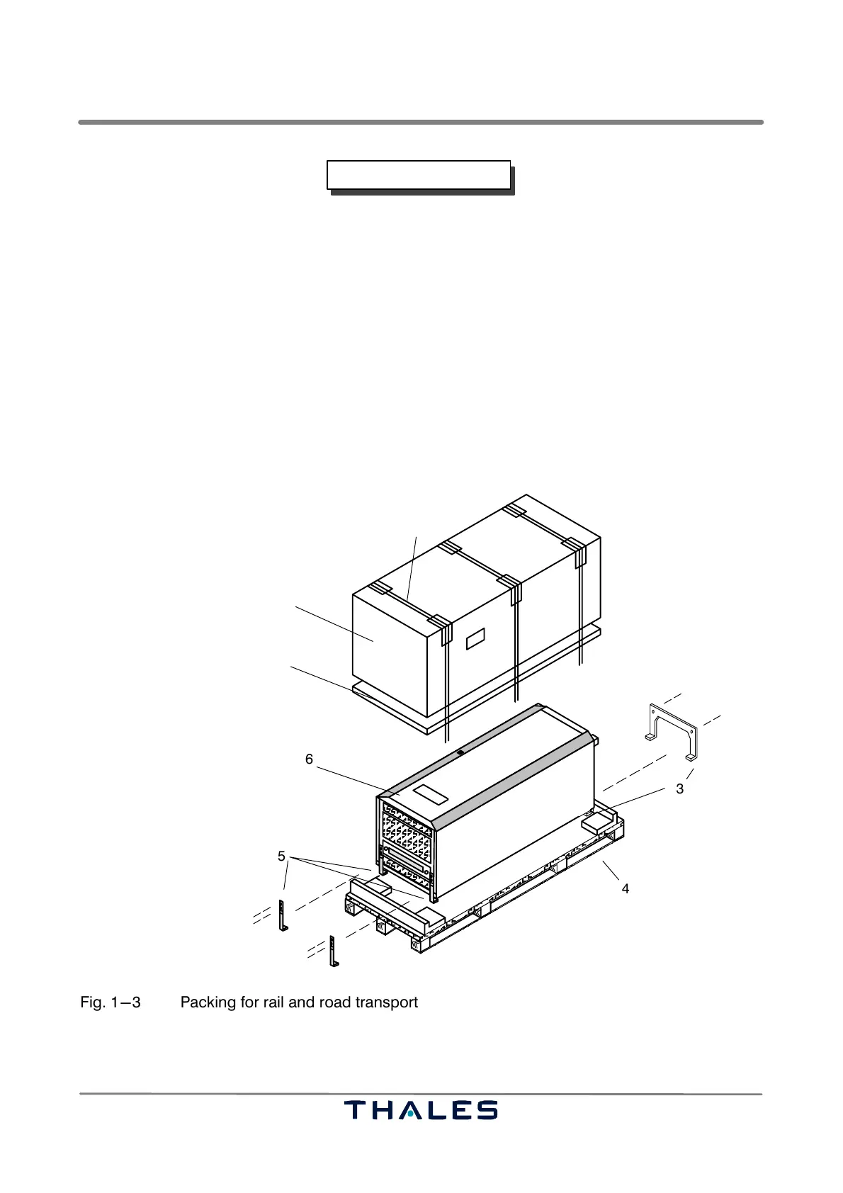
Hold the transmitter cabinet firmly in position until the support angles (Fig. 1−3/3 and 5)
have been dismantled. Pay special attention when removing the lower support angle.
− Undo the two screws (M10) left and right on the upper support angles (Fig. 1−3/5). Remove the
screws and washers and the upper support angles left and right. Tilt the transmitter cabinet (Fig.
1−3/6) forward slightly, hold it and dismantle the lower support angle (Fig. 1−3/3). Then carry the
transmitter cabinet to its point of installation and screw to the floor.
− Open the front door and remove the foam panel behind it.
− Close the front door.
Store away all despatch packaging (Fig. 1−3), so that it can be used again for transport purposes
if required. Use the original packaging components to repack. Repack the equipment and subassem-
blies as described above, but in reverse sequence.
1 Telescope box
2 Plastic ribbon
3 lower support angle
(ref. no. 36480 28009)
4 Pallet
5 upper support angle (2x)
(ref. no. 36385 28026)
6 Transmitter cabinet
7 Foam panel
1
2
7
ÄÄÄÄÄÄÄÄÄÄ
ÄÄÄÄÄÄÄÄÄÄ
ÄÄÄÄÄÄÄÄÄÄ
ÄÄÄÄÄÄÄÄÄÄ
ÄÄÄÄÄÄÄÄÄÄ
ÄÄÄÄÄÄÄÄÄÄ
ÄÄÄÄÄÄÄÄÄÄ
ÄÄÄÄÄÄÄÄÄÄ
ÄÄÄÄÄÄÄÄÄÄ
ÄÄÄÄÄÄÄÄÄÄ
ÄÄÄÄÄÄÄÄÄÄ
ÄÄÄÄÄÄÄÄÄÄ
ÄÄÄÄÄÄÄÄÄÄ
3
6
4
5
Fig. 1−3 Packing for rail and road transport