LLZ 421
Operation and Maintenance Installation
ILS 420
2−1Ed. 01.04
SOAC
CHAPTER 2
INSTALLATION
2.1 DETERMINING THE INSTALLATION SITE
The area in which a ILS Localizer is to be installed is determined by the responsible Civil Aviation Au-
thority according to the international air traffic regulations. The area is dependent on the necessary
obstacle clearance and the runway configuration (e.g. overrun, clearway, stopway). The installation
is determined by means of a site survey at which a surveyor must always be present. Thales ATM can
provide an engineering consultant on site for this survey.
2.1.1 Antenna System
The Installation of the antenna system is described in Part 3 Antenna System Description.
2.1.2 Location of LLZ−Shelter/Building
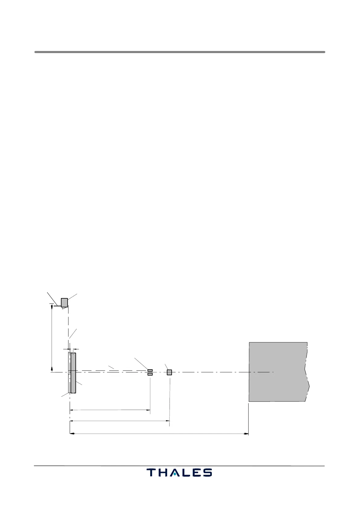
See Fig. 2−1.
The typical location of the LLZ shelter or building referenced to the extended center line is shown in
Fig. 2−1. It may be located left hand or right hand of the runway center line. The foundations for the
standard shelter are shown in Fig. 2−2.
NOTE: The shelter or building must be located behind and beside the antenna base as shown.
It shall be positioned in a way that the shelter door is situated in the direction of view to
the antenna but not to the weather side.
Shelter
Cable trench
Field dipole (optional)
Option: theodolite platform
Reflection area
Antenna
Power and
signal cable
typical 70
80 (120) (2F)
100 (140) (2F)
typical 300
NOTE:
Distances in ( ): antenna 21 elements
Shelter: either side of extended RWY center line
All distances in meters
1
RWY
center line
65 (1F)
85 (1F)
Cable trench
Fig. 2−1 Typical installation site with site survey control points