GR-5 Operator’s Manual
A-14
Connector Specifications
The GR-5 has one antenna connector for radio transmission/reception
and three port connectors for power and data upload/download.
Radio (Modem) RF Connector
The modem connector (Table A-8) is a reverse polarity TNC
connector for spread spectrum and a BNC connector for Digital and
Satel modem.
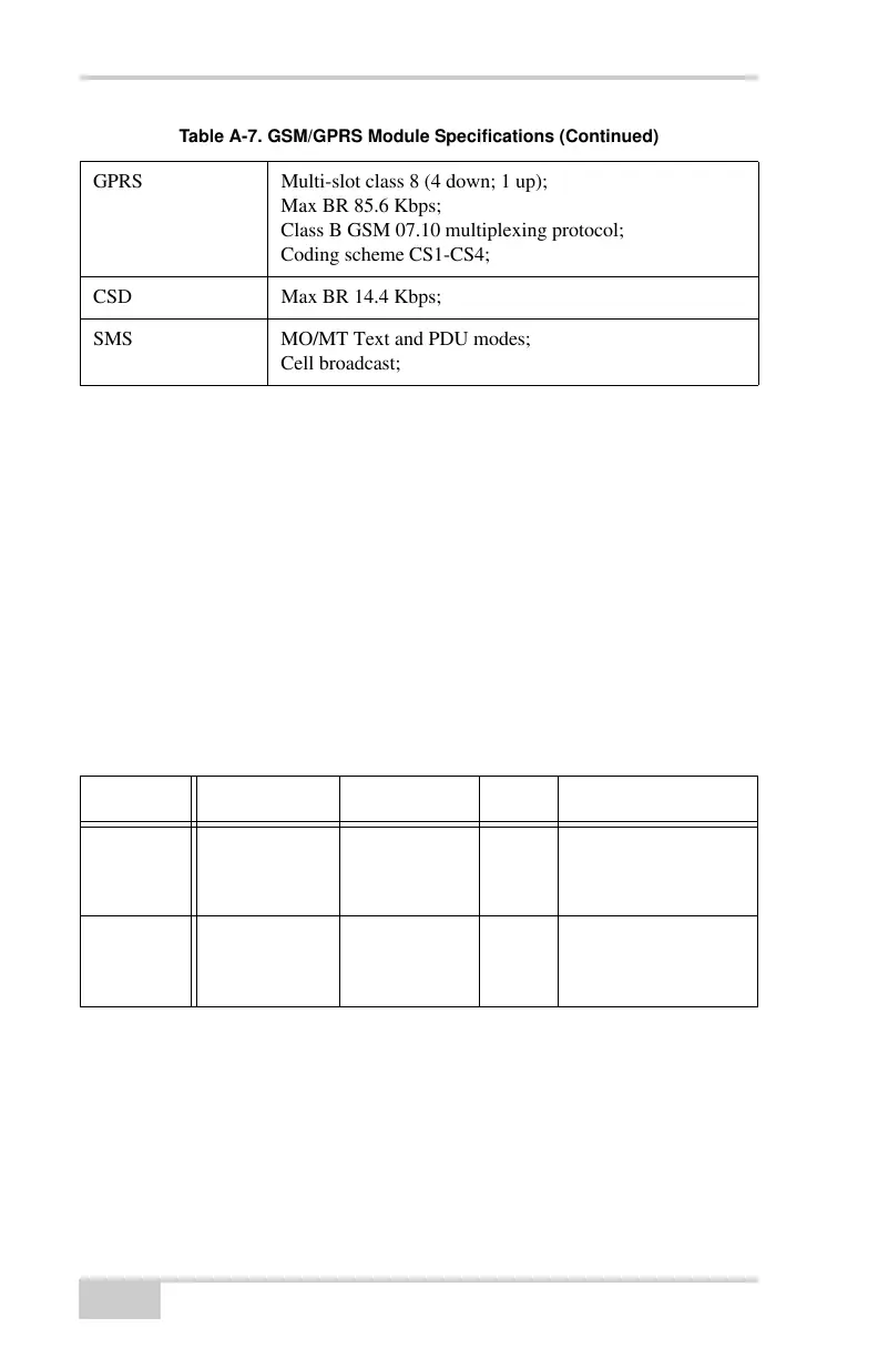
GPRS Multi-slot class 8 (4 down; 1 up);
Max BR 85.6 Kbps;
Class B GSM 07.10 multiplexing protocol;
Coding scheme CS1-CS4;
CSD Max BR 14.4 Kbps;
SMS MO/MT Text and PDU modes;
Cell broadcast;
Table A-8. Modem Connector Specifications
Modem Type Signal Type Dir Details
Spread
Spectrum
Reverse
polarity TNC
Modem I/O I/O RF/GSM input/
output to/from
modem antenna
Digital/
Satel
BNC Modem I/O I/O RF/GSM input/
output to/from
modem antenna
Table A-7. GSM/GPRS Module Specifications (Continued)