GR-5 Receiver
P/N 7010-1004
1-15
Data and Power Ports
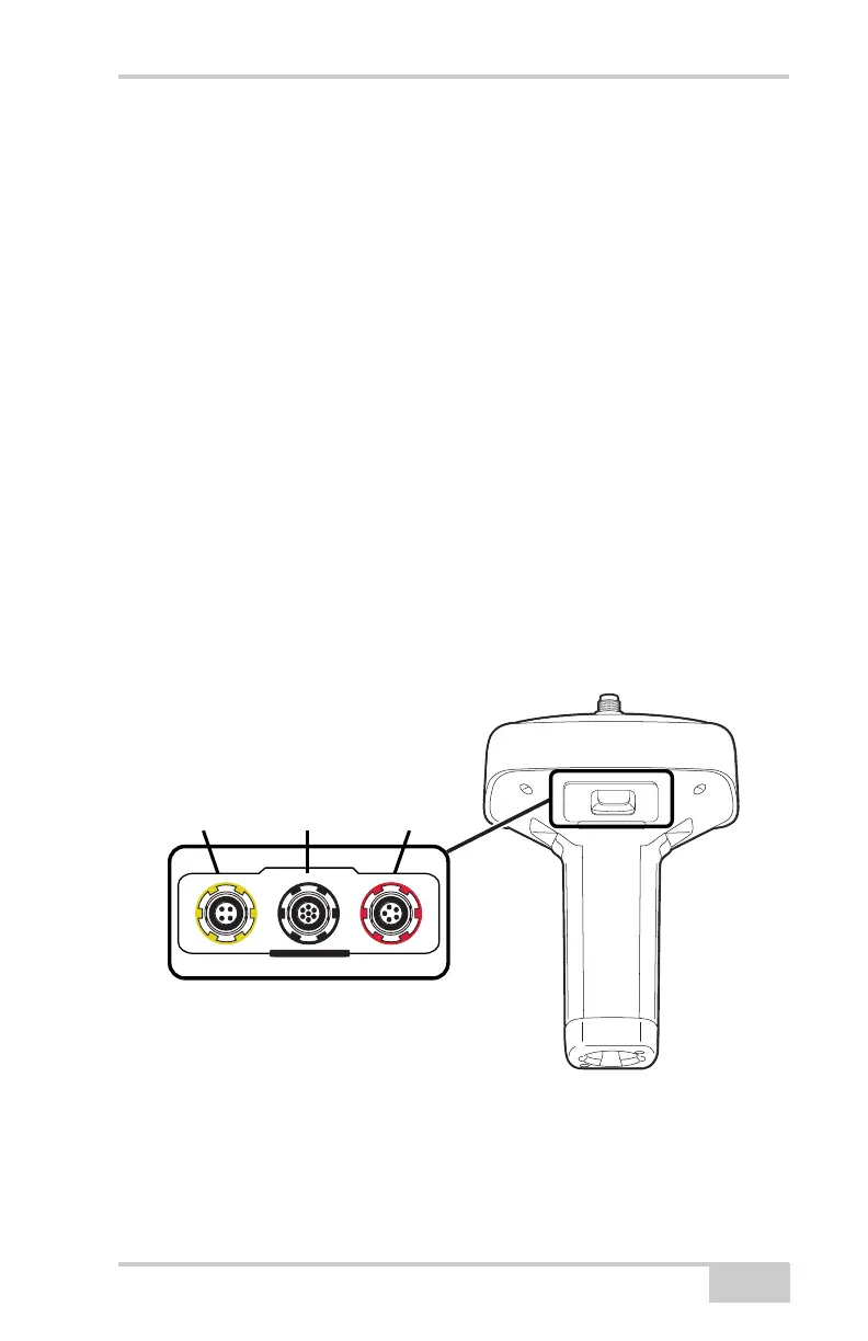
The GR-5 has the following three ports (Figure 1-3):
• USB – rimmed in yellow; used for high-speed data transfer and
communication between the receiver and an external device.
The body of the connector on the corresponding cable is yellow.
• Serial Port A– rimmed in black; used for communication between
the receiver and an external device.
• Serial Port B – used internally and left free in the current release.
• Serial Port C – used internally to connect the modem and receiver
boards.
• Serial Port D – used internally to connect the receiver board and
Bluetooth module.
• Power – rimmed in red; used to connect the receiver to an
external power source. This port can also be used to charge the
batteries.
The body of the connector on the corresponding cable is red.
Figure 1-3. GR-5 Ports
U
S
B
S
E
R
I
A
L
P
O
W
E
R
USB
(yellow)
Power
(red)
Serial
(black)