18
The S-4 Sculpting Sampler - Ofcial Manual
19
The S-4 Sculpting Sampler - Ofcial Manual
The hi resolution screen displays both parameter values and a functional
animation of the selected option. For example the material tape device
page will show the sample playback. If multiple pages exist, pressing the
device button repeatedly will cycle through each page and its parameters.
The display format style follows a generic structure and layout.
1.7 User Interface
The front panel controls are designed to encourage exploration and
experimentation giving fast and easy access to the wide range of
parameters and functions. There are some generic conventions that apply
globally when using the user interface.
NOTES
Getting Started
1
Buttons
Parameters & Value Knobs
Select Knob
Action Buttons
Selected buttons will illuminate brightly
when the function is selected.
Each of the 8 push / rotary knobs represent
the current display page parameters.
Any instruction will give the parameter name
relevant to the knob, i.e. Turn (SPEED).
Holding a knob while adjusting some
parameters will open a ‘mode select’ menu.
These parameters are shown with a
’
tag.
The select knob is a tactile push / rotary encoder
with detent rotation for iterative, precise changes.
This selects from menus and options. By default
this changes tempo 1 BPM increments.
The 4 Action buttons operate dynamically.
Their function changes to represent the option
currently displayed directly above the button.
Some parameters operate on a single scale i.e. 0-
100%, some have a bipolar range ie -50 to +50 and
others may be an option selection ie ‘Chromatic’
The selected function and its currently active
page parameter values can be adjusted by
the respective rotary knob. Pressing a page
button repeatedly will cycle through is pages.
Sometimes the illuminated button and color
represents its functions current state. The
button can be dim, static lit or ashing.
Flash during
playback
Getting Started
1
TAPE1 120.0
120 BPM
SPEED
TEMPO
START LENGTH
ROTATE XFADE
LOAD MONITOR OVERDUB RECORD
0.0 4:0
TAPE1 120.0
120 BPM
SPEED
TEMPO
START LENGTH
ROTATE XFADE
LOAD MONITOR OVERDUB RECORD
0.0 4:0
(SPEED) (START)
(ROTATE)
Unipolar Bipolar Options
(TEMPO) (LENGTH)
(XFADE)
Octaves
1/4 Quantize
Length4:0
NOTES
PITCH
LEVEL
START LENGTH
LOOP XFADE
LOAD LOOP
POLY1
AMP
FLTR
Big Bass.wav
120.0
AMP
FLTR
Big Bass.wav
MAPPING: MOD 21 120.0
PITCH
LEVEL
START LENGTH
LOOP XFADE
MOD 1 MOD 2 MOD 3 MOD 4
POLYSAMPLER1 120.0
PITCH
LOOPSTART
STRETCH START LENGTH
LOOPLENGTH CUTOFF RESONANCE
MOD 1
MOD 2 MOD 3 MOD 4
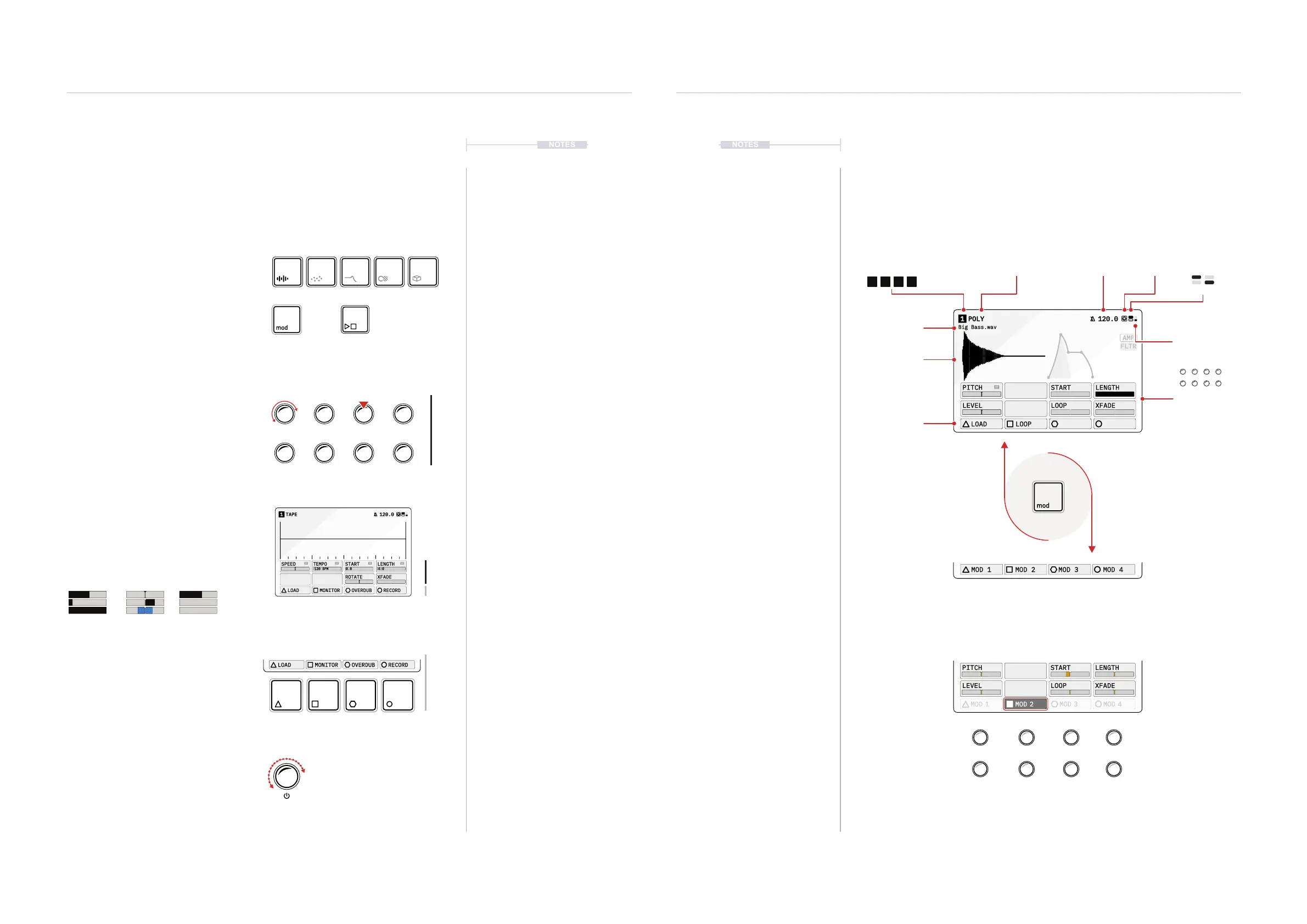
Current Track Device or Modulator Global Tempo
Modulation Mapping
Pitch
Level
Start
Loop
Length
XFade
Main Function View
Animated
Main Function
Active Sample
Action Button
Options
The [MOD] Button will switch the action buttons between the device specic actions and
the modulation mapping. In modulation mapping view, the active modulator will
illuminate its corresponding action button in color. The parameter values now represent
the amount of modulation applied to each parameter.
Modulation amount applied to each parameter.
Adjusted in this mode with the 8 parameter control knobs.
8 Parameter
Values per Page
Main Out
Audio Level
MIDI In Page #
1 2
1 2 3 4