80
The S-4 Sculpting Sampler - Ofcial Manual
81
The S-4 Sculpting Sampler - Ofcial Manual
NOTES
NOTES
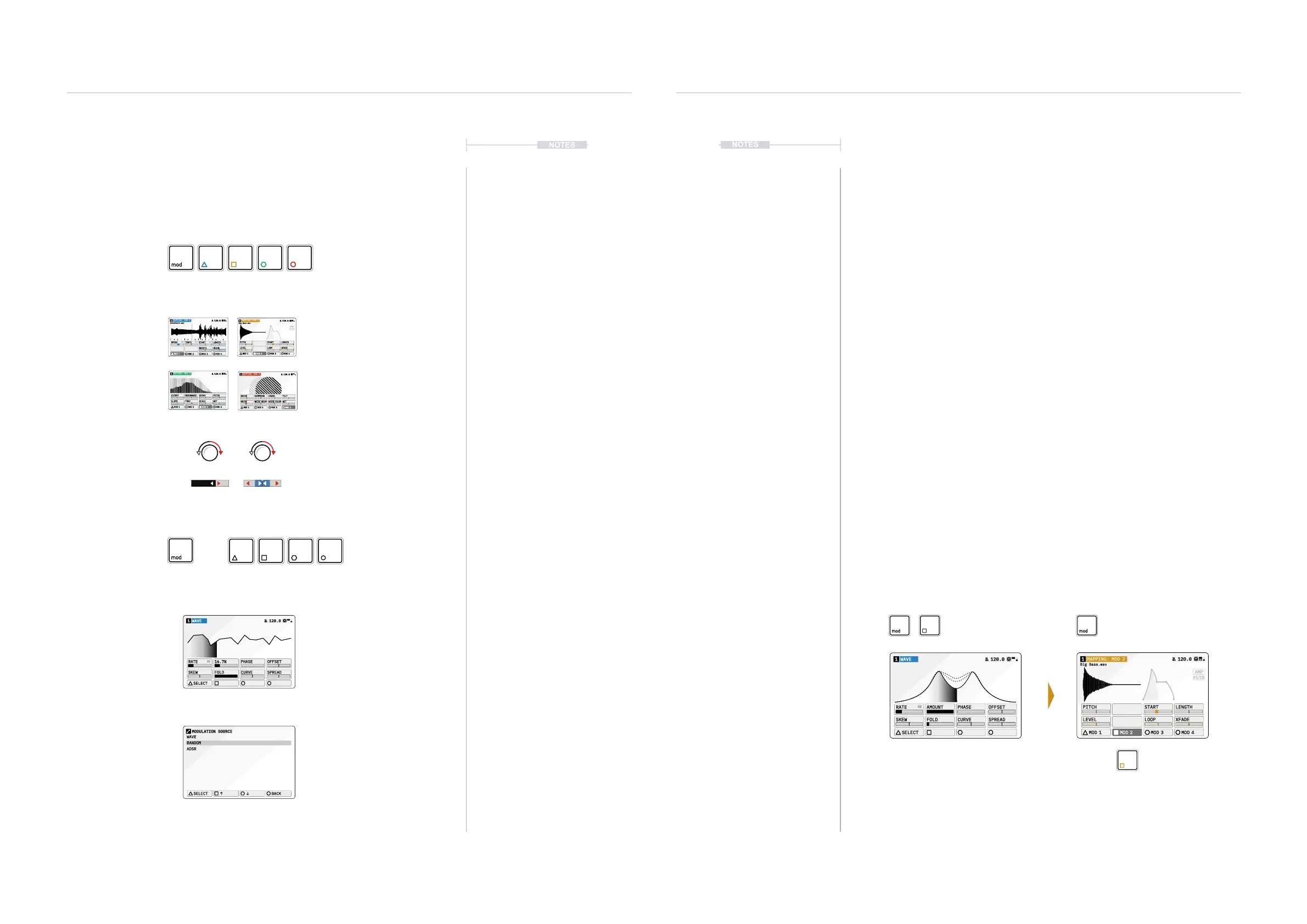
Modulation slot selection and assigning a modulator source to a slot is an
intuitive process. The currently selected device is shown in color next to the
track number in the audio device display header. The action button color
also indicates the represented slot.
Map and set amount
8 parameter knobs adjust the
modulation amount. Value range is
unipolar or bipolar when using CTRL.
WAVE1 120.0
SELECT
RATE 16.7% PHASE OFFSET
SKEW FOLD CURVE SPREAD
WAVE
RANDOM
ADSR
SELECT
BACK
MODULATION SOURCE
AMP
FLTR
Big Bass.wav
MAPPING: MOD 21 120.0
PITCH
LEVEL
START LENGTH
LOOP XFADE
MOD 1 MOD 2 MOD 3 MOD 4
Audio or Mixer Page.
Select Modulation Slot
Change or Select a
slot Modulator model.
Modulator Page
Modulator Selection
Pop Up Page
Modulation Options
on the device Page
+
Action buttons represent
modulation slots for track
Press [MOD] for Selection of
the Mod slot and modulator
parameters to edit.
Press [LOAD] to select and
change the modulator.
Select modulator to
load to the slot *.
Press [MOD] on the destination page
to show the modulation amounts and
the selected Mod source 1-4.
Press Action button for modulator
source slot to map to a parameter.
Colors Blue, Yellow, Green and Red
represent the modulator slots 1-4.
Hold Press
* Double Tap a [MODx] when displaying a destination page to quickly and directly access the modulation page.
Mod 1 Mod 2 Mod 3 Mod 4
Modulators
4
Modulators
4
▌ MODULATING A PARAMETER
1. Select a track to edit. Press [TRACK], then select a track using the
action buttons located under the screen display.
2. Choose a destination function. For example [MATERIAL]
for the
Material device. The page is displayed.
3. Press [MOD] to switch to Modulation mapping view. Mod will illuminate
and the selected function page will be titled as ‘Mapping: Mod X’, where
‘X’ is the currently selected modulation slot.
4. Select a modulation source slot, Press [MOD 1] … [MOD 4]. This
selects the slot with the modulator device assigned to the selected slot
for the track. The color scheme for the headline and action button will
reect the modulation slot.
5. In the modulation view, the 8 parameters now reect the amount of
modulation applied to each parameter.
• Turn the parameter knob 1-8 to adjust the amount of modulation
applied to the selected control parameter from the chosen mod slot.
This will affect the destination in a unipolar style.
• Hold [CTRL] + Turn parameter knob 1-8 to adjust the amount of
modulation applied to the selected control parameter from the
chosen mod slot. This will affect the destination in a bipolar style.
• Press [MOD] to exit the modulation mapping view.
WAVE1 120.0
SELECT
RATE AMOUNT PHASE OFFSET
SKEW FOLD CURVE SPREAD
AMP
FLTR
Big Bass.wav
MAPPING: MOD 21 120.0
PITCH
LEVEL
START LENGTH
LOOP XFADE
MOD 1 MOD 2 MOD 3 MOD 4
Modulation Cong+ Modulation Mapping
Modulator Source Page Destination Device Page
Unipolar Bipolar
Turn [Ctrl] + Turn
MAPPING: MOD 11 120.0
SPEED TEMPO START LENGTH
ROTATE XFADE
MOD 1 MOD 2 MOD 3 MOD 4
DronePart1.wav
MAPPING: MOD 31 120.0
CUTOFF RESONANCE DECAY PITCH
SLOPE TONE SCALE WET
MOD 1 MOD 2 MOD 3 MOD 4
DRIVE COMPRESS CRUSH TILT
NOISE
NOISE DECAY
NOISE COLOR
WET
MOD 1 MOD 2 MOD 3 MOD 4
MAPPING: MOD 41 120.0