114
TA117
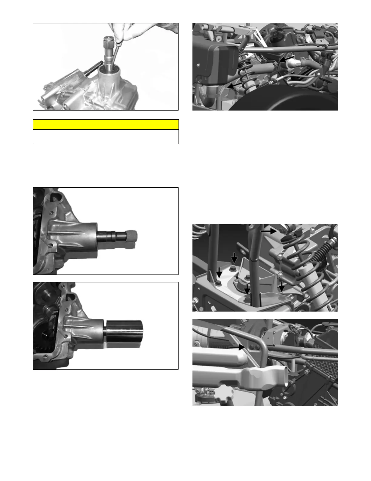
2. Wipe any oil or dirt from the seal area of the transaxle.
3. Tape the splined portion of the pinion shaft to protect
the seal; then using an appropriate seal installer,
install the front output seal (approximately 0.5-1.0
mm deep).
TA129
TA130
REMOVING TRANSAXLE
1. Remove seat, right- and left-hand side panels, rear
rack and fender, and right- and left-hand footwells
(see Steering/Body/Controls section).
2. Disconnect the oxygen (O2) sensor. Remove exhaust
springs and nuts holding exhaust pipe to engine.
Remove pipe.
NOTE: Muffler does not need to be removed.
OHA130
3. Put vehicle on support stand and remove tires, hubs
(see Hub Assembly section) and drive axles (see
Drive Axles section).
4. Remove clutch covers, rear duct and clutch (see
Engine/Transmission section).
5. Disconnect taillight from wiring harness, remove
two push clips and cut any cable ties holding harness
to upper frame. Note locations of cable ties for
assembly. Move wiring harness out of the way.
6. To remove upper frame: Remove upper bolts holding
rear shocks to frame. Remove four cap screws hold-
ing rear upper frame to lower frame and four bolts
(two on right side, two on left side) holding front
upper frame to frame. Remove upper frame.
OHA116
OHA117
7. On left side, remove two cap screws securing tran-
saxle mounting bracket to engine.
CAUTION
Do not drive the awl too far or bearing damage will
occur.