46
FI580
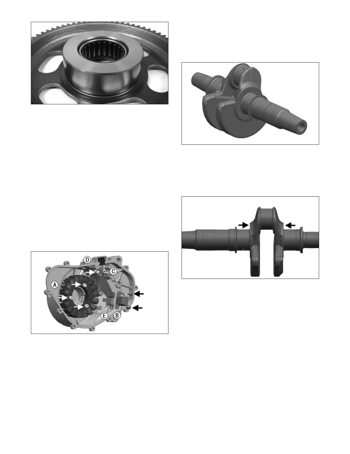
INSPECTING STATOR COIL/MAGNETO
COVER ASSEMBLY
1. Inspect the stator coil for burned or discolored wir-
ing, broken or missing hold-down clips, or loose cap
screws.
2. Inspect the bearings in the magneto housing for dis-
coloration, roughness when rotated, and secure fit in
bearing bores.
REPLACING STATOR COIL/
CRANKSHAFT POSITION SENSOR
1. Remove the three cap screws securing the stator coil
(A), two cap screws securing the crankshaft position
sensor (B), and one cap screw from the upper cable
hold-down (C).
2. Lift the rubber grommet (D) out of the housing; then
remove the stator coil/crankshaft position sensor.
Account for and note the position of the stator wire
harness hold-down (E) under the crankshaft position
sensor.
LYC048
3. Install the new stator coil assembly and secure with
three new cap screws coated with Loctite 243.
Tighten to 80 in-lb (9 N-m).
4. Place the stator wire harness hold-down into posi-
tion; then install the crankshaft position sensor and
secure with two cap screws. Tighten securely.
5. Install the upper cable hold-down and secure with a
cap screw. Tighten securely.
CRANKSHAFT
Measuring Crankshaft (Runout)
1. Place the camshaft on a set of V blocks; then position
the dial indicator contact point against the shaft and
zero the indicator.
LYC045
2. Zero the indicator and rotate the crankshaft slowly.
3. Maximum runout must not exceed specifications.
Measuring Crankshaft (Web-to-Web)
1. Using a calipers, measure the distance from the par-
allel axial shoulders.
LYC044
2. Acceptable width range must not exceed specifica-
tions.
3. Shoulders should not show signs of seizure.
Crankshaft Bearings
1. Inspect all crankshaft bearing journals, connecting
rod (conrod) big end bore, and the crankcase crank-
shaft bores for scoring, seizure marks, or pitting.
2. If excessive scoring, seizure marks, and/or pitting is
found, the crankshaft, conrod or crankcase must be
repaired or replaced.
3. Bearing size and grade are designated on the crank-
shaft web. The first three letters designate crankshaft
bearings starting at magneto side and moving to PTO
side (see GL1, GL2, and GL3 in illustration
LYC062), and the letter after the hyphen designates
the conrod bearing (see HL1 in illustration LYC062).
For example, ABB-C is read as: A = main journal 1;
B = main journal 2; B = main journal 3; and C = con-
rod journal.