75
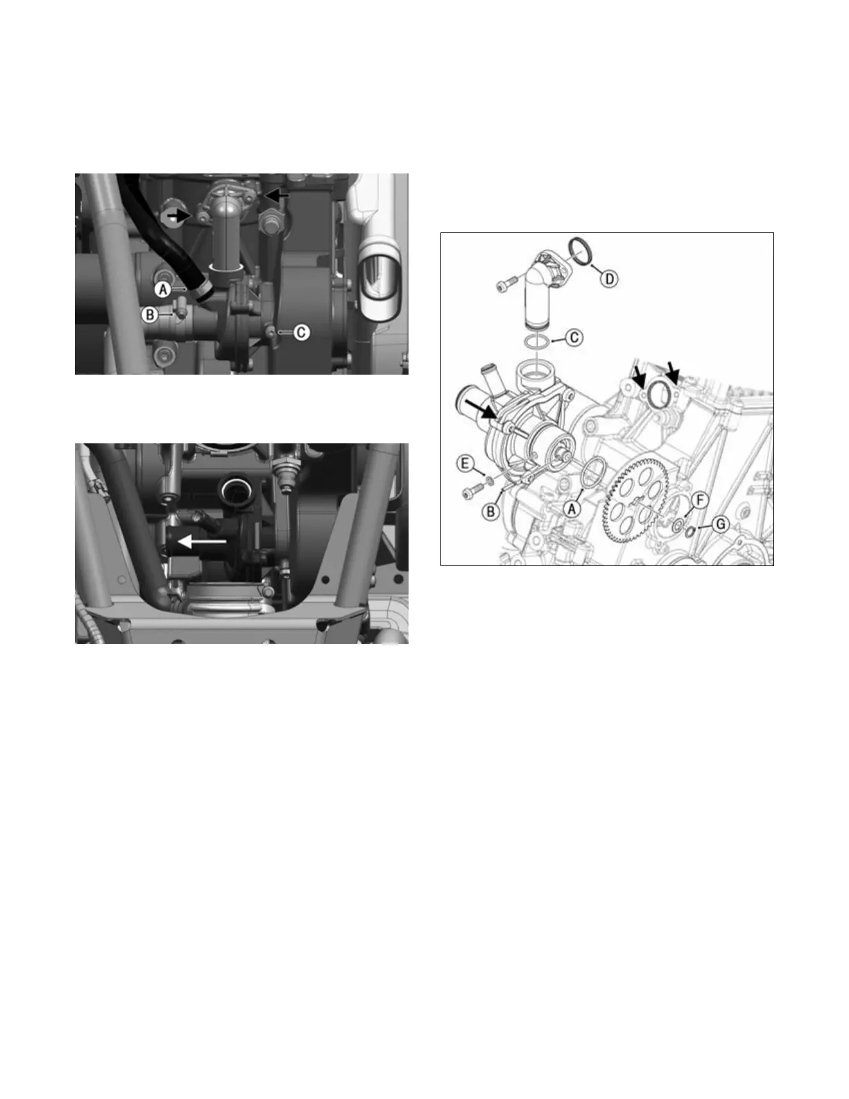
11. Loosen the lower hose clamp (B) and slide the clamp
away from the hose end approximately 2 in (5 cm);
then remove hose from the water pump.
12. Remove the two M6 screws securing the water pump
to the engine and the M6 set screw (C), and discard
copper washer; then rotate the water pump far
enough to remove plastic elbow.
OHA083
13. Remove pump by pulling straight back and out of
engine housing. Avoid tilting water pump when
removing from engine housing bore.
OHA134
Installing
1. Place a new O-ring (A) on new pump using O-ring
grease. Then position pump shaft across the hole
horizontally and insert cross pin (B) using a drop of
liquid sealant or high-viscous grease to prevent the
pin from sliding out during installation.
2. Insert the pump straight into engine housing. Avoid
tilting inside the bore.
3. Replace O-ring (C) and rubber seal (D) on the plastic
elbow using O-ring grease. Assemble the plastic
elbow on water pump and rotate into place. Secure
elbow to engine with two M6 fasteners. Secure pump
with M6 set screw and new copper washer (E).
4. Ensure cross pin is still in place and horizontal. Cor-
rect the angle of the pump shaft with a Torx T30
drive if needed. Lift the gear wheel onto pump shaft.
Find the correct angle to match the gear wheel
groove to the shaft cross pin and push the gear wheel
fully onto the pump shaft.
5. Place washer (F) carefully on shaft using a pointed
screw drive that allows washer to slide onto shaft.
Install a new circlip (G) using the correct spring ring
pliers. DO NOT over bend circlip and ensure proper
location on water pump shaft.
OHA135
6. Install a new O-ring on plastic cover using O-ring
grease. Reassemble cover with cover lip orientated at
the top, apply Loctite 243 and secure with two M6
fasteners. Tighten to 35 in-lb (4 N-m).
7. Connect the two coolant hoses to the water pump and
secure with new upper hose clamp and existing
lower hose clamp. Tighten securely.
8. Fill the cooling system with the proper amount of
recommended coolant (see Periodic Mainte-
nance/Tune-up section). Check for leaks.
9. Replace CVT cover, inlet duct and intake duct.
10. Replace throttle body (see Throttle Body sub-sec-
tion) and engine air intake.
11. Install left footwell, left- and right-hand side panel
and seat (see Steering/Body/Controls section).