74
C. The thermostat should start to open at 160-187° F
(71-86° C).
D. If the thermostat does not open, it must be
replaced.
3. Inspect all coolant hoses, connections, and clamps
for deterioration, cracks, and wear.
NOTE: All coolant hoses and clamps should be
replaced every four years or 4000 miles (6400 km).
Installing
1. Place the thermostat and O-ring into the thermostat
housing; then secure the thermostat housing to the
cylinder head with the two cap screws.
2. Fill the cooling system with the recommended
amount of antifreeze (see Periodic Mainte-
nance/Tune-up). Check for leakage.
NOTE: There is a bleed screw located on the ther-
mostat housing (see illustration OHA122 above) that
should be loosened up or removed when filling the
radiator from an empty state. This allows air to be
bled from the system.
COOLING FAN
Removing
1. Remove the radiator (see OHA122 in this sub-sec-
tion).
2. Remove the fan assembly from the radiator.
Installing
1. Position the fan assembly on the radiator; then secure
with existing hardware.
NOTE: The fan wiring must be in the upper-right
position.
2. Install the radiator.
WATER PUMP
NOTE: The water pump is a non-serviceable com-
ponent. It must be replaced as an assembly.
Removing
1. Remove the radiator cap and drain the coolant from
radiator.
NOTE: Drain coolant by removing drain plug or
lower hose.
2. Remove seat, left- and right-hand side panel and left
footwell (see Steering/Body/Controls section).
3. Remove throttle body (see Throttle Body sub-sec-
tion) and engine air intake.
4. Remove CVT cover, inlet duct and intake duct.
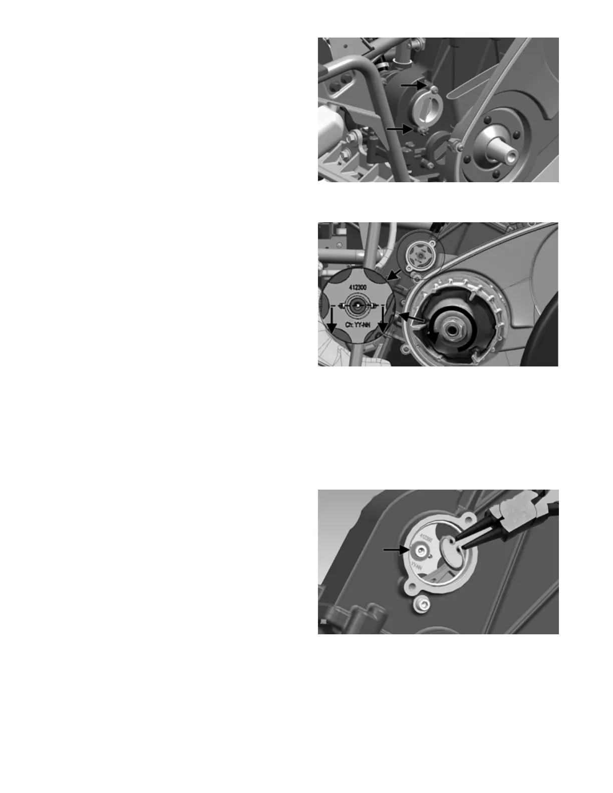
5. Remove two M6 fasteners that secure the upper
round plastic cover. Remove the cover.
OHA131
6. Watch the cross pin on the water pump axle and
rotate the CVT clutch until pin is horizontal.
OHA132
NOTE: For better access to internal water pump
parts, remove clutches and inner clutch cover.
7. Choose the correct spring ring pliers and carefully
remove circlip by putting tips into the holes, then
remove washer behind circlip using a bar magnet.
NOTE: If circlip and washer fall into engine, engine
must be removed from the vehicle to retrieve the parts
(see Engine/Transmission section).
OHA133
8. Remove gear wheel from water pump shaft and lay it
aside in the engine. (It can still be accessed through
the opening by hand or bar magnet). If the gear
wheel needs replacing, see Engine/Transmission sec-
tion.
9. Using a bar magnet, remove the cross pin. DO NOT
remove remaining circlip and washer.
10. Remove upper hose clamp (A) and discard. Remove
hose.