Chapter 3 BMTX BCU mounting, installing, and power wiring
24 BMTX-SVN01C-EN
3. Connect the circuit board’s 60-pin ribbon cable to the termination
board’s 60-pin slot.
The connector is keyed to the slot. If you have difficulty connecting it,
make sure that the key is lined up with the slot.
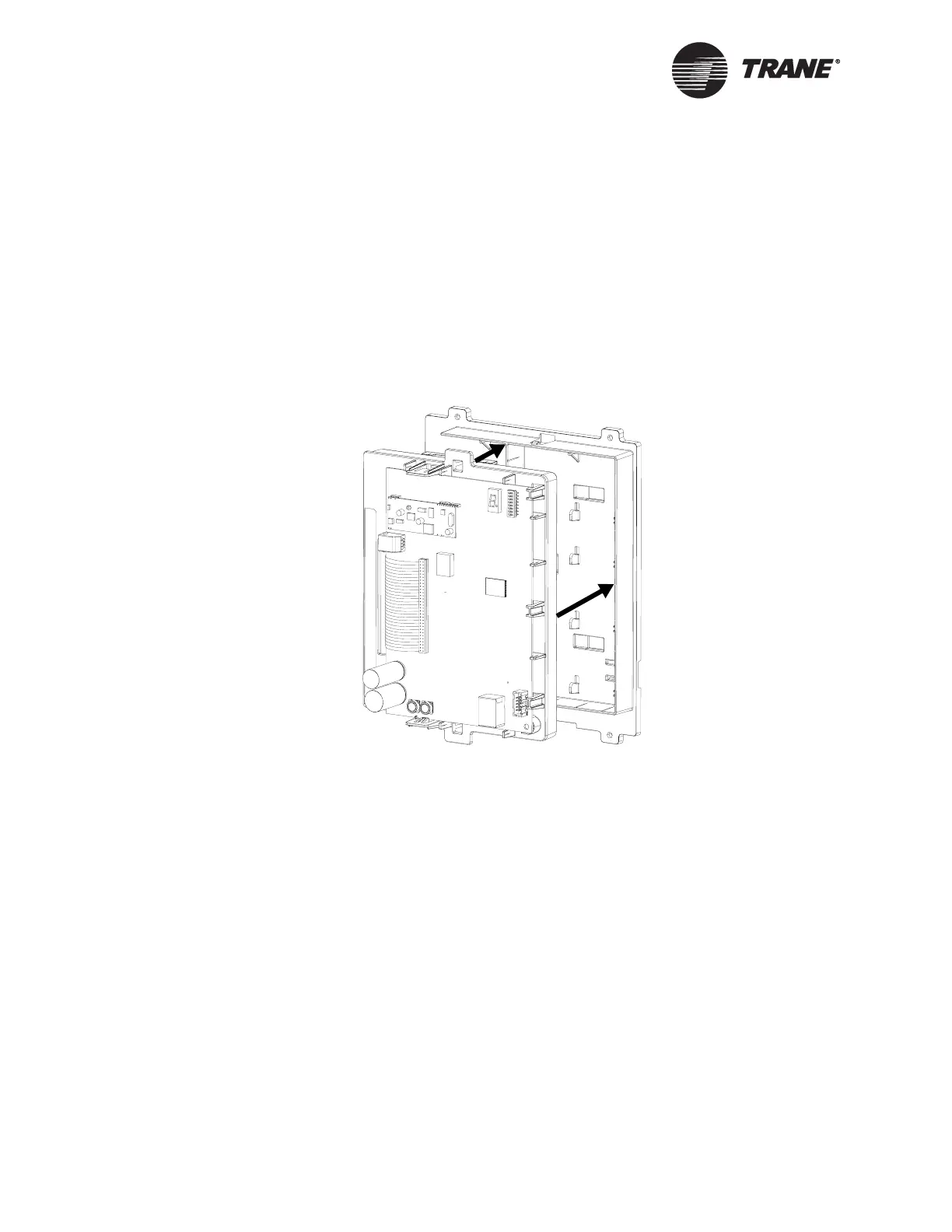
4. Align the snaps on the circuit board frame with the mounting locks at
opposite ends of the enclosure back, as shown in Figure 12.
5. Using the tabs that are at both ends of the top frame, push the two
frames together. You will hear a click when the frames connect.
Figure 12. Connecting the frames
6. For controllers with an operator display, connect the operator-display
cable to the circuit board. (See Figure 13 on page 25.)
7. Connect the 24 Vac power cable to the termination board. The seven-
segment LED display should light up.
8. Connect the Ethernet cable to the Ethernet connector on the circuit
board.
9. Connect the telephone cable to the modem connector on the circuit
board.
 Loading...


