I⁄O Extender Modules 117
Chapter 3 System Description
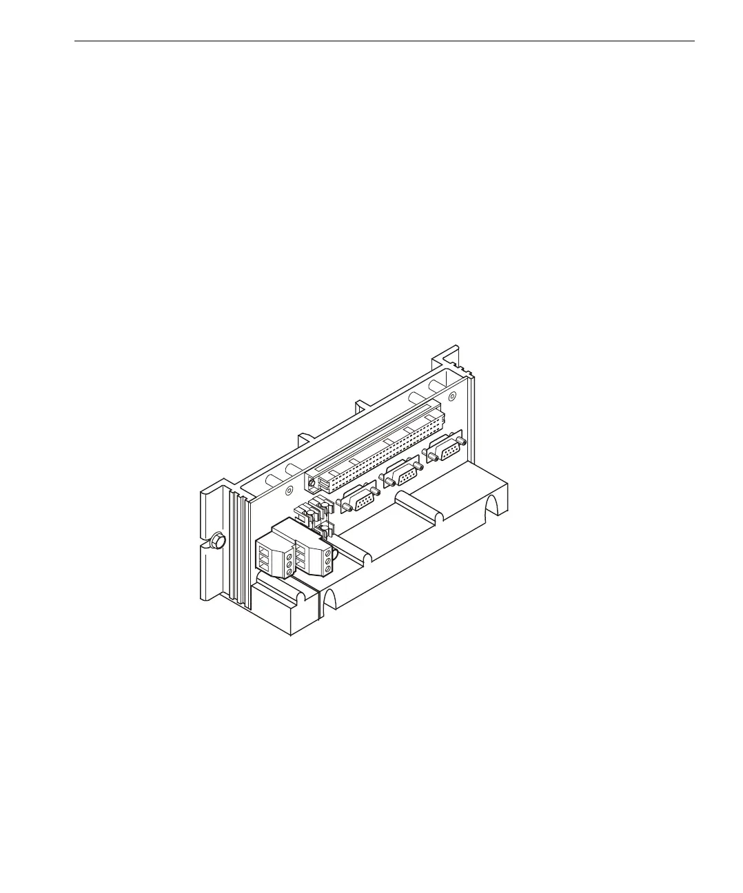
Connecting I⁄O Extender Modules
An I⁄O Extender Module is connected to the top, bottom, or both top and bottom of
a column of baseplates. If a column of baseplates contains an MP Baseplate, logic
power may be connected to the I⁄O Extender Module or to the MP Baseplate. If a
column of baseplates does not contain an MP Baseplate, logic power can be
connected to the I⁄O Extender Module at the top of the column or to the I⁄O
Extender Module at the bottom of the column.
The I⁄O bus TMR connections should be daisy-chained through each column of
baseplates with an MP Baseplate at the beginning of the column. For long I⁄O
buses, the baseplate furthest from the MP should be connected to an I⁄O Extender
Module with I⁄O bus termination plugs. Three separate I⁄O bus cables connect from
I⁄O Extender Module to I⁄O Extender Module. For the installation procedure, see
“I⁄O Extender Modules” on page 115.
I⁄O Extender
Module