Guidelines 135
Chapter 4 Installation and Maintenance
the maximum logic and field power for all modules installed on a baseplate.
(Field power is the percentage of field circuit power that is dissipated within
the controller.) If spares are present, add the same amount of logic power as
the primary modules.
For more information about cooling, contact the Triconex Customer Response
Center.
Calculating Logic Power
Note Information in this section is based on a fault condition in which only one
of the redundant power sources is operational. Under normal operating conditions,
both power sources share the load.
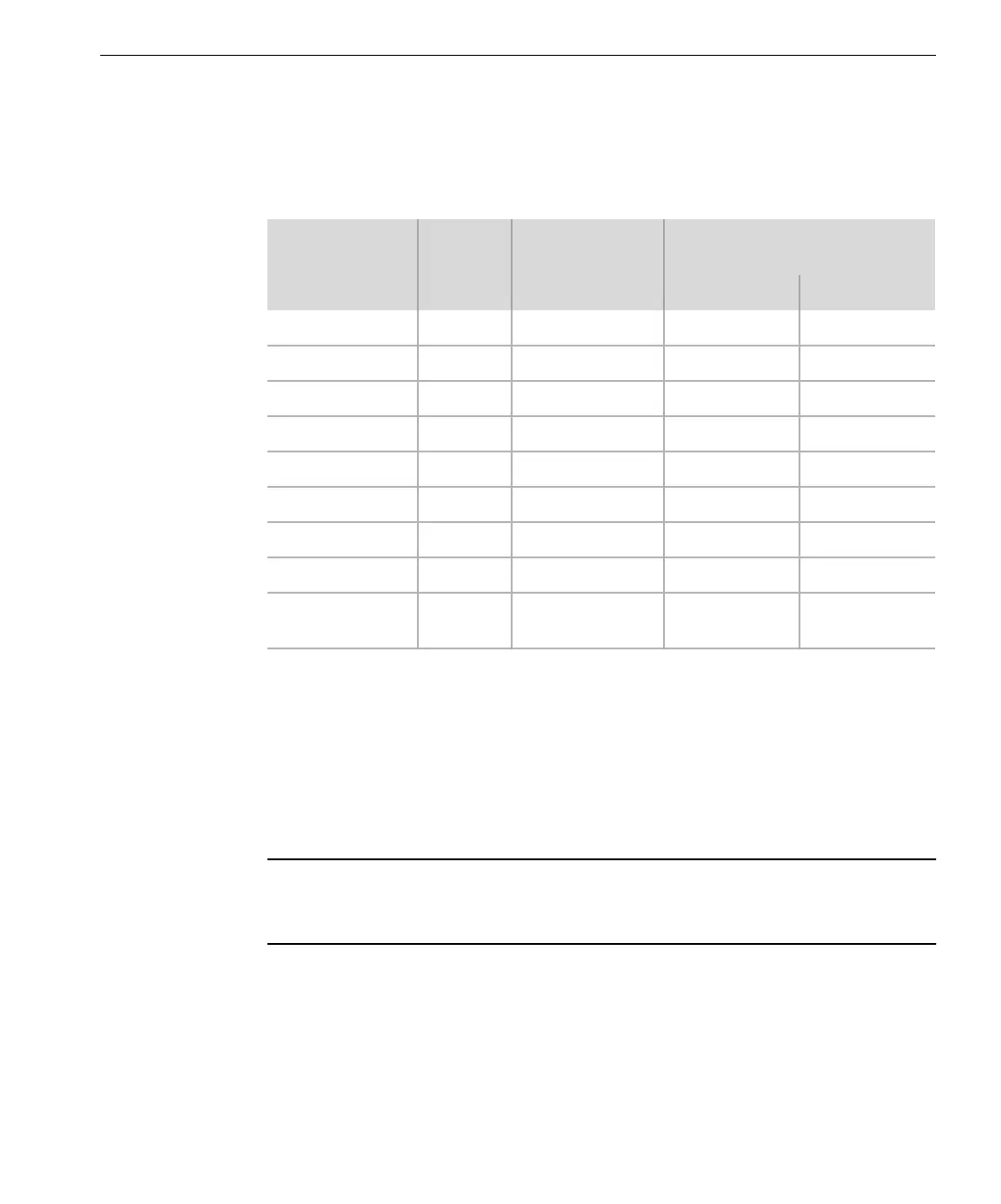
To determine the maximum logic power supply needed, use the following table to
sum the maximum logic power for all modules, including hot spares, to be installed
on a baseplate.
Module
Model
Number
Maximum
Logic Power
(Watts)
1
1. To convert watts to British thermal units: BTU = watts x 3.414
Maximum Field Power
(Watts)
Primary Spare
Analog Input 3351 3 4 Negligible
Analog Output 3481 3 3 Negligible
Analog Output 3482 3 7 Negligible
Communication 3201 8 Not applicable Not applicable
Digital Input 3301 3 7 Negligible
Digital Output 3401 3 4 Negligible
Main Processor 3101 8
2
2. Without MAUs
Not applicable Not applicable
Pulse Input 3381 3 Negligible Negligible
Solid-State
Relay Output
3451 3 4 Negligible