System Overview 27
Chapter 3 System Description
Configuration
An assembly consists of a module and a baseplate. Three types of assemblies are
available:
• Main Processor
• Communication
•I⁄O
A basic Trident system consists of one MP assembly, an optional CM assembly,
and up to 14 I⁄O assemblies. If AO or PI Modules are included, up to 10 I⁄O
assemblies are allowed.
Assemblies are configured into a system on a mounting plate using interconnect
assemblies, extenders, I⁄O bus cables, and I⁄O bus terminators. I⁄O modules
communicate with the MPs by means of a triplicated, RS-485, bi-directional
communication bus, called the I⁄O bus.
The I⁄O bus cable can be used to join I⁄O columns. Maximum cable length is up to
6 meters (20 feet) without termination or up to 200 meters (650 feet) with
termination.
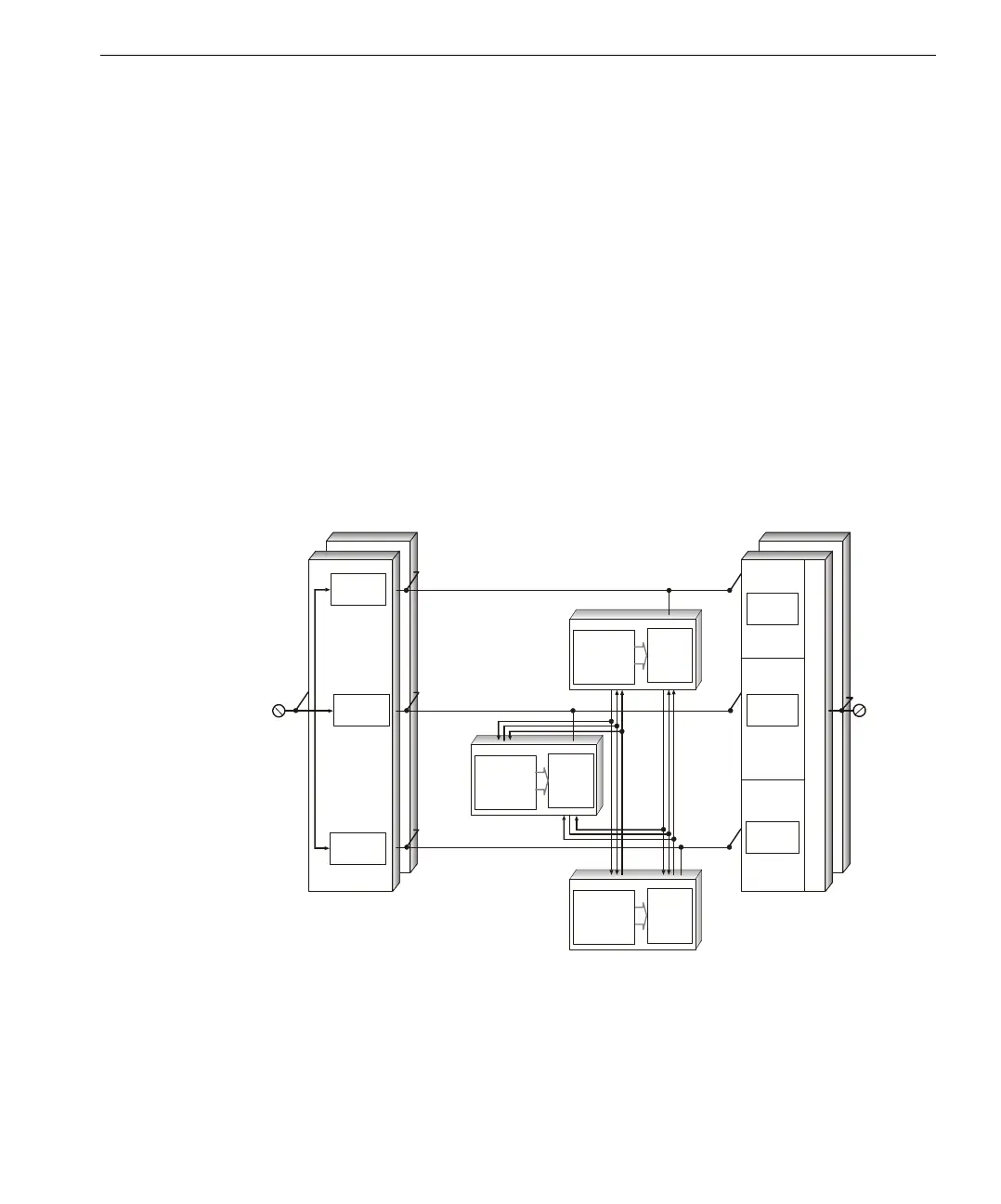
Typical System
Configuration
Input Module
Hot Spare
Field
Input
Input
Channel A
Input
Channel B
Input
Channel C
Tr iB us & Tr iT im e
Diagnostic Channel
Channel A I/O Bus
Field
Outpu
Channel B IO/ Bus
Channel C I/O Bus
MP A
IOP A
MP B
IOP B
IOP C
(SX)
(SX)
(IOX)
(IOX)
(IOX)
utput Module
Hot Spare
MP C
(SX)
Output
Channel A
Output
Channel B
Output
Channel C
Output Voter