204 MP Baseplate Connectors
Trident Planning and Installation Guide
RS-485 Pin-Outs
RS-485 Signal Descriptions
RS-485 signals are transmitted over a cable of twisted-pair-wires. The polarity of
the 2-to-6-Volt differential between the two wires indicates whether the data is
marking or spacing. If terminal A is negative with respect to terminal B, the line is
marking. If terminal A is positive with respect to terminal B, the line is spacing.
The maximum cable length is dependent on the wire used. For example, using 24-
AWG twisted-pair wire, the maximum length is 1.2 kilometers (4000 feet), but can
be extended using modems. The following table describes the RS-485 signals.
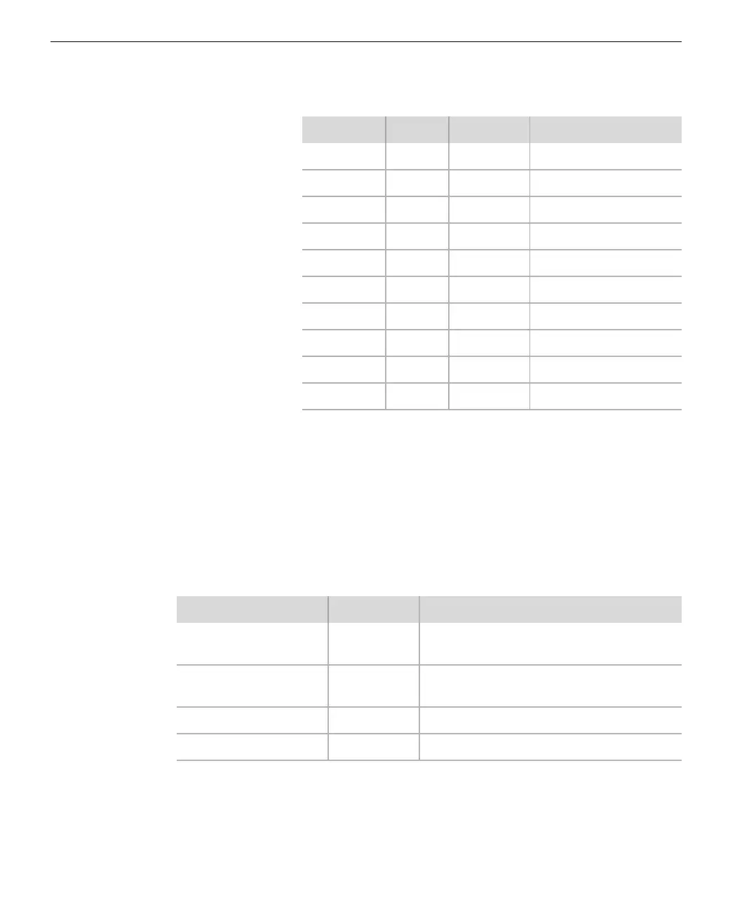
DB-9 Pin Signal Direction RS-485 Function
1— — —
2 RD-A In Receive data
3 SD-A Out Transmit data
4— — —
5 GND — Signal ground
6— — —
7 SD-B Out Transmit data, invert
8 RD-B In Receive data, invert
9 OUT Term 5 V DC through 1k Ω
Housing Shield — Safety ground
Signal Designator Description
Transmit Data
Transmit Data, Inverted
SD-A
SD-B
MP transmits serial data
Receive Data
Receive Data, Inverted
RD-A
RD-B
MP receives serial data
Signal Ground GND Signal ground
5 V DC through 1k Ω Not used