4 Controller Architecture
Trident Planning and Installation Guide
Controller Architecture
The controller features TMR architecture to ensure fault tolerance and error-free,
uninterrupted control in the event of hard failures of components or transient faults
from internal or external sources.
Each I⁄O module houses the circuitry for three independent channels. Each channel
on the input modules reads the process data and passes that information to its
respective MP. The three MPs communicate with each other using a proprietary,
high-speed bus called the TriBus.
Once per scan, the MPs synchronize and communicate with their neighbors over
the TriBus. The TriBus forwards copies of all analog and digital input data to each
MP and compares output data from each MP. The MPs vote the input data, execute
the application, and send outputs generated by the application to the output
modules. In addition, the controller votes the output data on the output modules as
close to the field as possible to detect and compensate for any errors that could
occur between the TriBus voting and the final output driven to the field.
For each I⁄O module, the controller can support an optional hot-spare module. If
present, the hot-spare takes control if a fault is detected on the primary module
during operation. The hot-spare position is also used for the online hot repair of a
faulty I⁄O module.
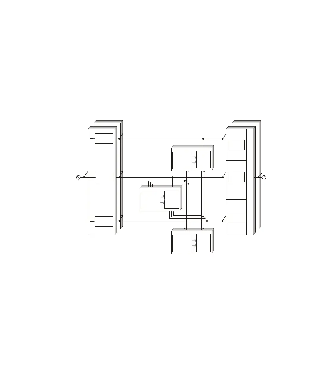
Simplified Block
Diagram
Input Module
Hot Spare
Field
Input
Input
Channel A
Input
Channel B
Input
Channel C
Tr iB us & Tr iT im e
Diagnostic Channel
Channel A I/O Bus
Field
Outpu
Channel B IO/ Bus
Channel C I/O Bus
MP A
IOP A
MP B
IOP B
IOP C
(SX)
(SX)
(IOX)
(IOX)
(IOX)
utput Module
Hot Spare
MP C
(SX)
Output
Channel A
Output
Channel B
Output
Channel C
Output Voter