220 Diagread Cables and Debug Connectors
Trident Planning and Installation Guide
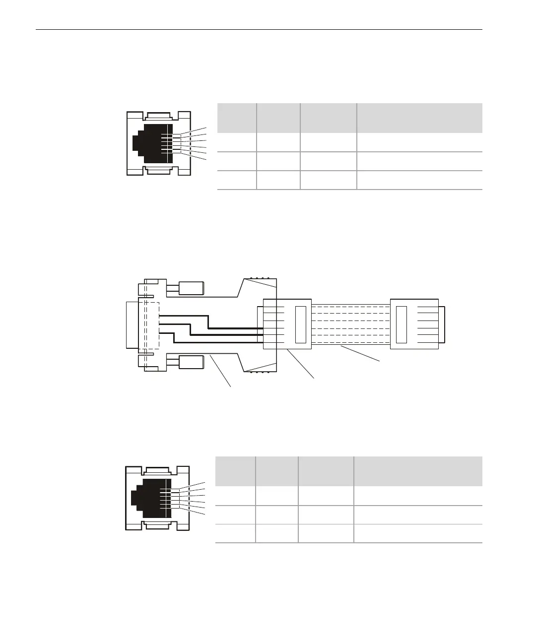
Debug Connector for Left-Position CMs
For the left-position CM, the Debug connector uses pins 1, 2. and 3.
I⁄O Modules and Right-Position CMs
Diagread Cable
Debug Connector for I⁄O Modules
For the I⁄O modules, the Debug connector uses pins 4, 5 and 6.
RJ-12
Pin
Signal Direction Description
1 TXD Out CM Diagread Transmit Data
2 RXD In CM Diagread Receive Data
3 GND — CM Ground
1
2
3
4
6
RJ-12
Pin
Signal Direction Description
4 TXD Out IOP Diagread Transmit Data
5 RXD In IOP Diagread Receive Data
6 GND — IOP Ground
2
3
5
1
2
3
4
5
6
1
2
3
4
5
6
I/O and
Left-Position CM
Debug Connector
Diagread
able
9-pin D-Sub-to-Modular
6-pin RJ-12 Adapter
Straight-Through RJ-12 Cable
(standard 6-wire telephone cable
1
2
3
4
6