16 Controller Architecture
Trident Planning and Installation Guide
System Diagnostics and Status Indicators
The controller incorporates online diagnostics. These diagnostics and specialized
fault monitoring circuitry are able to detect and alarm all single-fault and most
multiple-fault conditions. The circuitry includes—but is not limited to—I⁄O loop-
back, watch-dog timers, and loss-of-power sensors. Using the alarm information,
the response of the system can be customized to the specific fault sequence and
operating priorities of the application.
Each module can activate the system integrity alarm, which consists of normally
closed (NC) relay contacts on each MP Module. Any failure condition, including
loss or brown-out of system power, activates the alarm to summon plant
maintenance personnel.
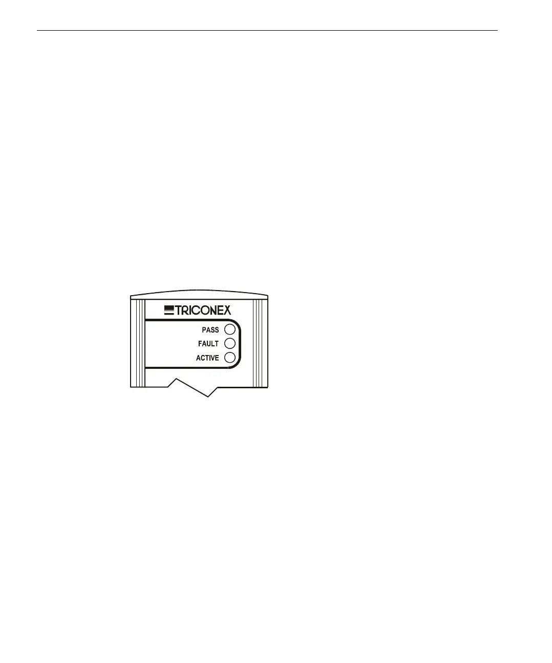
The front panel of each module provides light-emitting-diode (LED) indicators that
show the status of the module or the external systems to which it may be connected.
Pass, Fault, and Active are common indicators. Other indicators are module-
specific.
Normal maintenance consists of replacing plug-in modules. A lighted Fault
indicator shows that the module has detected a fault and must be replaced.
All internal diagnostic and alarm status data is available for remote logging and
report generation. Reporting is done through a local or remote TriStation or host
computer. For more information on reporting, see the TriStation 1131 Developer’s
Guide.
Front Panel
Indicators