206 CM Baseplate Connectors
Trident Planning and Installation Guide
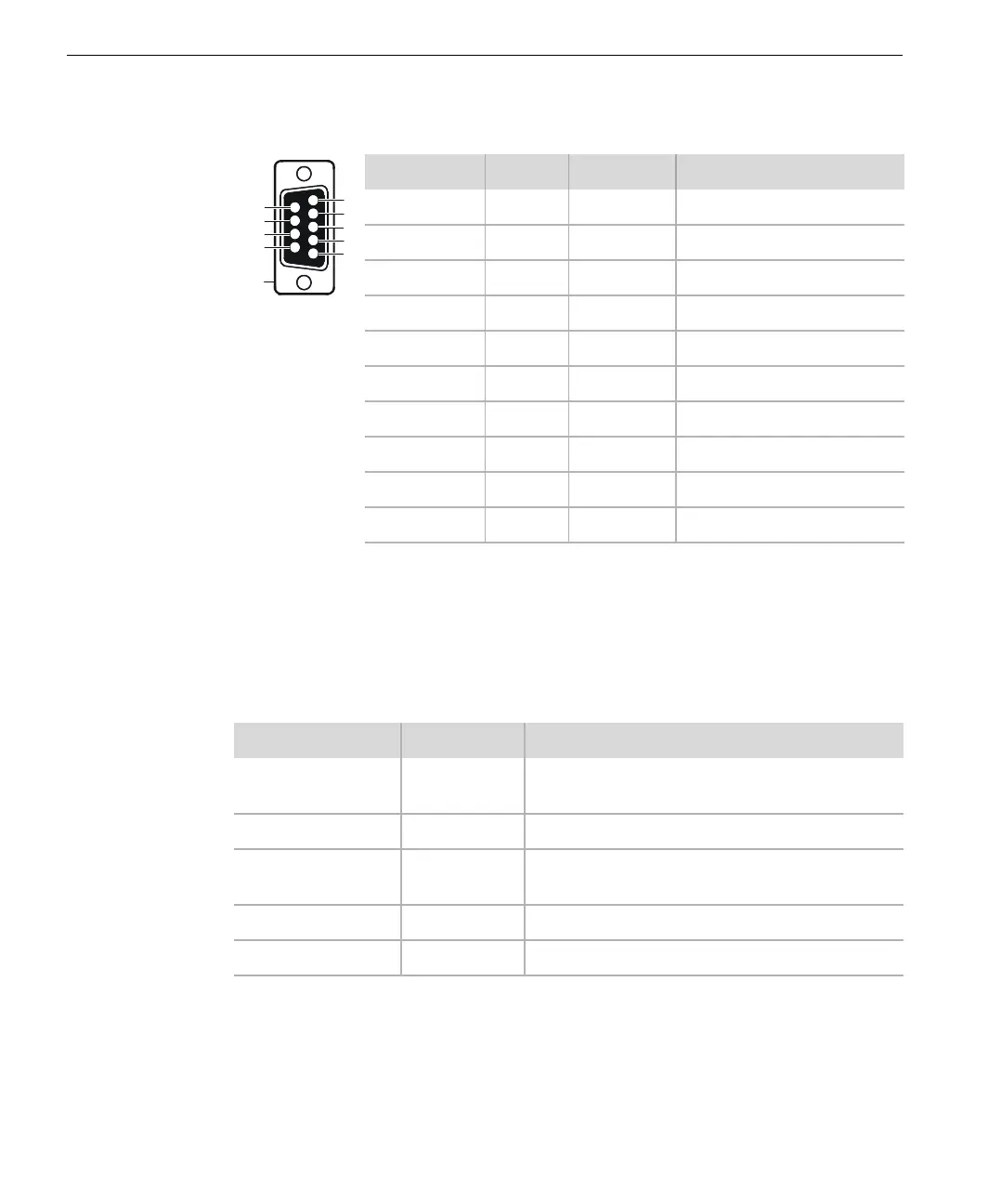
RS-232 Pin-Outs
RS-232 Signal Descriptions
Spacing (on or 0) occurs when RS-232 signals are between +6 and +12 V DC;
marking (off or 1) occurs when they are between –6 and –12 V DC. The maximum
cable length is 15 meters (50 feet), but can be extended using modems. The
following table describes the RS-232 signals.
DB-9 Pin Signal Direction RS-232 Function
1 CD In Carrier detect
2 RXD In Receive data
3 TXD Out Transmit data
4 DTR Out Data terminal ready
5 GND — Signal ground
6 DSR — Not used (data set ready)
7 RTS Out Request to send
8 CTS In Clear to send
9 RI — Not used (ring indicator)
Housing Shield — Safety ground
Signal Designator Description
Clear to Send CTS MP ignores CTS and transmits data as soon as it
is available
Request to Send RTS MP turns on RTS unconditionally
Data Carrier Detect DCD MP ignores DCD and always accepts data from
RXD
Transmit Data TXD MP transmits serial data
Receive Data RXD MP receives serial data
7
8
9
2
3
4
5
1
6
Shield