Trident Planning and Installation Guide
APPENDIX D
Non-Incendive Circuit Parameters
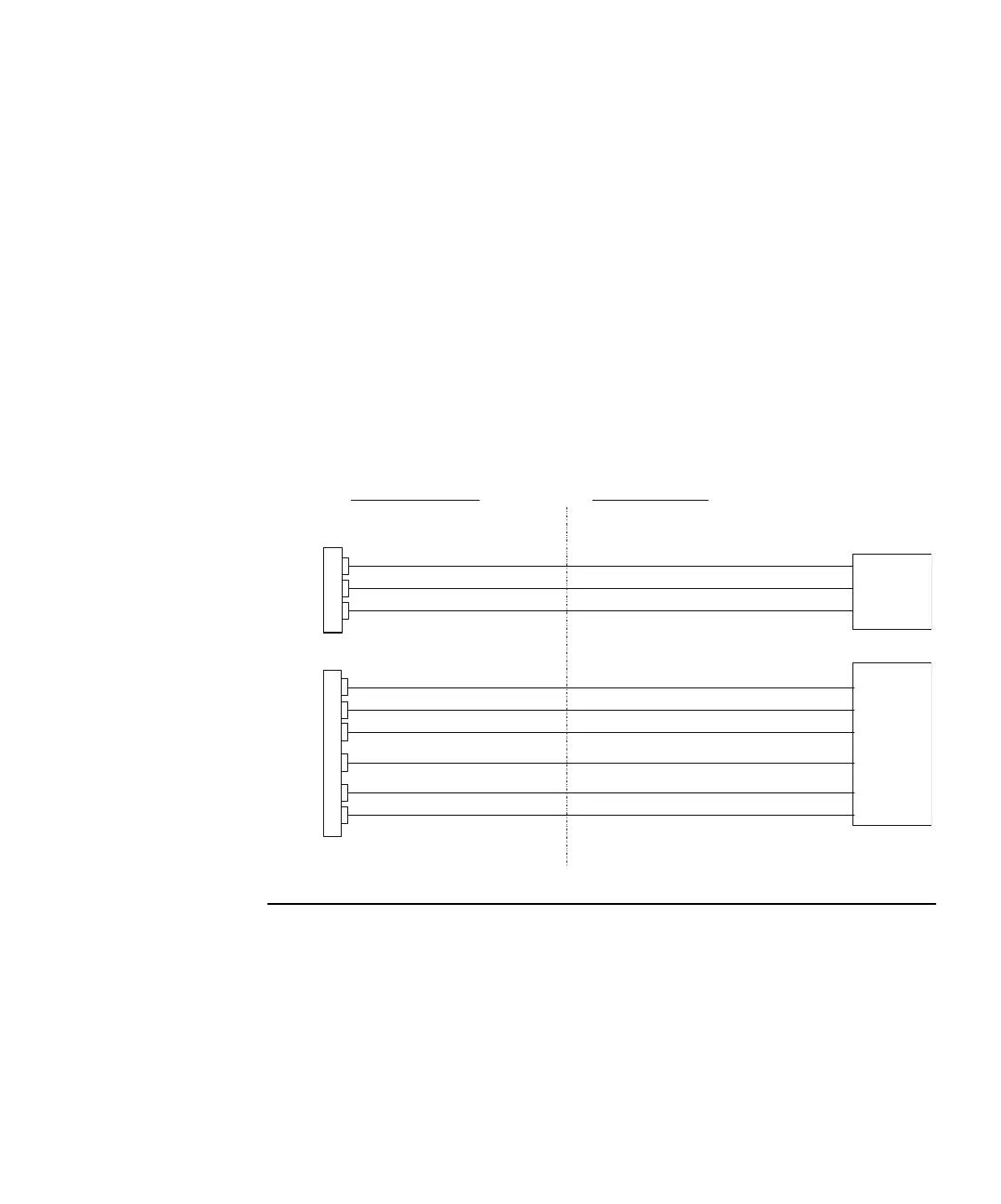
Special parameters apply to Main Processor Modules and Communication
Modules for non-incendive communication circuits in the field. These parameters
are shown in the following drawing, which are extracted from Triconex Drawing
9110043-001, REV. A.
Note 1 FMRC-approved apparatus. The voltage (Vmax) and current (Imax) that
the load device can receive must be equal to or greater than the maximum open
circuit voltage (Voc) and maximum short circuit current (Isc) that can be delivered
by the source device. In addition, the maximum capacitance (Ci) and inductance
(Li) of the load, which is not prevented by circuit components from providing a
stored energy charge to the field wiring (for example, diode across a winding to
clamp an inductive discharge), and the capacitance and inductance of the
Schematic of
Non-Incendive
Communication
Circuits
NETWORK (9) SHIELDED TWISTED PAIR IN/OUT SIGNALS
(9) SHIELDED TWISTED PAIR IN/OUT SIGNALS
(9) SHIELDED TWISTED PAIR IN/OUT SIGNALS
(9) SHIELDED IN/OUT SIGNALS
(9) SHIELDED IN/OUT SIGNALS
(9) SHIELDED IN/OUT SIGNALS
(9) SHIELDED IN/OUT SIGNALS
(5) IN/OUT SIGNALS
(3) IN/OUT SIGNALS
NETWORK #1
NETWORK #2
SERIAL PORT #2
SERIAL PORT #1
SERIAL PORT #3
SERIAL PORT
RS-232 DIAG READ
RS-232 DIAG READ
MP
Model
3101
CM
Model
3201
ASSOCIATED
APPARATUS
(NOTE 1)
ASSOCIATED
APPARATUS
(NOTE 1)
LASS 1, DIV 2
HAZARDOUS LOCATION
LASS 1, DIV 2
OR NON-HAZARDOUS