Solid-State Relay Output Module Indicators 193
Chapter 5 Fault and Alarm Indicators
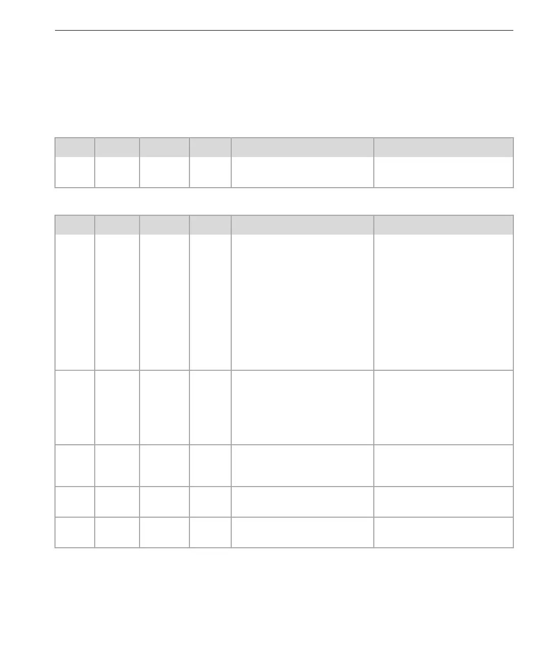
SRO Status Indicators
The SRO status indicators identify the processing state for the SRO Module.
A fault light indicates that the module has an internal fault.
Normal State
Pass Fault Active Lock Description Action
Green
steady
No
light
Green
steady
No
light
Module is operating normally. No action is required.
Fault States
Pass Fault Active Lock Description Action
Green
steady
No
light
No
light
No
light
Possible conditions include:
Application has not been loaded
into the MP.
If the module is the hot spare,
no action is required.
Application has been loaded
into the MP, but has not been
started up.
Module has just been installed
and is currently running start-up
diagnostics.
The other module is active.
If the module is active, replace
module.
No
light
Red
steady
—
1
No
light
Possible conditions include:
Module may be in the process
of power-up self-test.
If the Pass indicator does not
go on within five minutes,
replace the module.
Module has detected a fault. Module is operational, but
should be replaced.
Module has detected marginal
input voltage in a steady-state
condition.
Check sensor signal strength.
Check sensor positioning.
—— — Red
steady
Module is unlocked from the
baseplate.
Lock module using a #2 flat-
blade screwdriver.
Green
steady
Red
steady
— — Indicators/signal circuitry on
the module are malfunctioning.
Replace the module.
1. This symbol ( — ) means the indicator is not important for this condition.