216 RS-485 Modbus Serial Cables
Trident Planning and Installation Guide
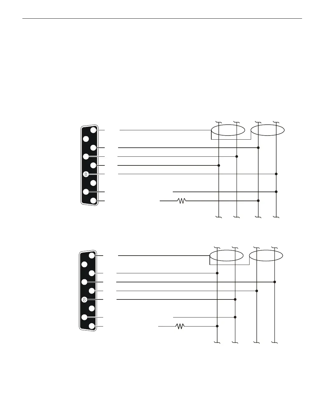
on the distance between branches.The following figures show these connections as
they should be made at the MP or CM.
When an MP or CM is a slave in a multi-point network, multiple transmitters
connect to the same conductor. One transmitter can be active at any time;
otherwise, the signal is distorted. Therefore, each node must be in the tristate (or
off) mode. To set the tristate mode for the MP and CM, set the Handshake mode to
Hardware using the Setup dialog box in TriStation’s Hardware Allocation screen.
RS-485 Modbus
Slave Network
1
6
7
9
2
3
4
5
CM or MP
Serial Port
Shield
RD-A
RD-B
5 VDC through 1 K
1 K
(optional)
Signal Ground (optional)
SD-A
SD-B
Ω
Ω
RD-A SD-A
Trunk R Trunk T
Network Trunk
RD-B SD-B
RS-485 Modbus
Master Network
1
6
7
9
2
3
4
5
Shield
RD-A
RD-B
5 VDC through 1 K (optional)
Ω
Signal Ground (optional)
SD-A
SD-B
RD-A SD-A
Trunk R Trunk T
Network Trunk
RD-B SD-B
1 K
Ω
CM or MP
Serial Port