8 Controller Architecture
Trident Planning and Installation Guide
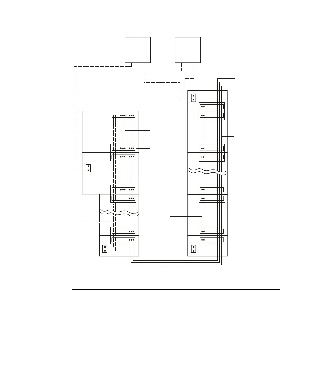
Note Each column of modules must have a separate logic power connection.
Field signal distribution is local to each I⁄O baseplate. Each I⁄O module transfers
signals to or from the field through its associated baseplate assembly. The two I⁄O
module slots on the baseplate tie together as one logical slot. The right or left
position holds the active I⁄O module and the other position holds the hot-spare I⁄O
module. Each field connection on the baseplate extends to both active and hot-
I⁄O Bus and Power
Distribution
Diagram
~~~
(14 I/O
Modules
Maximum)
(8 I/O
Modules
Maximum
Per Column
Power
Supply
#1
Power
Supply
#2
Interconnect
Assembly
Communication
Bus
Power
Bus
Power
Bus
Channel A
Channel B
Channel C
I/O Bus
EM
EMEM
I/O
CM
MP
I/O
I/O
I/O
I/O Bus
I/O Bus