Pag. 39
Smontaggio Riduttore
-descrizione generale
1
-
Gearbox disassembly
-general description
1
-
1 Descrizione dettagliata dello smontaggio-
montaggio del ponte è disponibili in versione
separata
2 I numeri tra parentesi si riferiscono alla posizio-
ne indicata nelle liste ricambi
1 Detailed description of disassembly-assembly of
axle are available in separate document
2 Numbers in brackets refer to the parts as listed
in the spare part list
Scaricare l’olio sia del gruppo freno che
del riduttore rimuovendo i tappi (76 e 78
magnetico)
2
nella parte inferiore e i tappi
(76 e 79) nella parte superiore (vedi fig 8a
pag. 11). Svitare le 16 viti (81,85,86) (vedi
fig. 8b pag. 11) dopo aver correttamente
imbragato il gruppo riduttore. Disaccoppia-
re e togliere il gruppo riduttore mantenedo-
lo in asse ed esercitando forza con una ido-
neo attrezzo nelle apposite 4 sedi ricavate
sul bordo della scatola stessa. Porre atten-
zione nel compiere tale operazione al fine
di non danneggiare le spine (74) e le spine
(73). Nel caso che una spina (73) rimanga
incastrata nel corpo (7/8), è necessario e-
strarla e riposizionarla nella sua sede sulla
flangia (16/17).
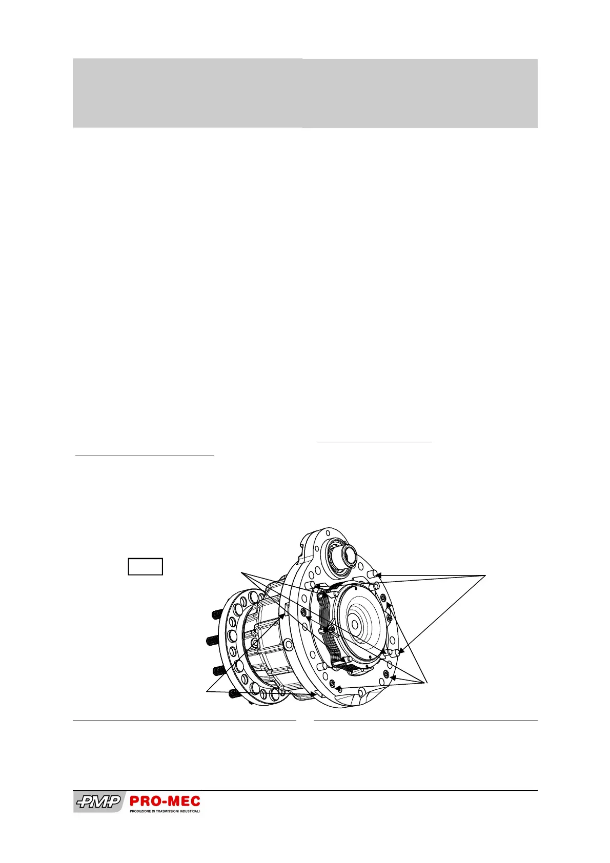
Smontaggio Flangia (16/17)
Svitare le 4 viti (84) sulla flangia (16/17)
e togliere la flangia esercitando forza con
una idoneo attrezzo nelle apposite 4 sedi
ricavate sul bordo della
flangia stessa.
You have to drain the oil both from the
brake disc chamber and from the reduction
gearbox, removing the plugs (76 and 78
magnetic)
2
from the bottom side and the 2
plugs (76 and 79) on the top (see fig page
11). Secure the gear box and then unscrew
the 16 screws (81,85,86) (see fig 8b page
11). Remove the box inserting a tool in the
4 seats on the edge of the box and pulling it
along the wheel axis. Please, pay attention
during this operation in order to avoid
damaging the pins (74) and the pins (73). In
case one pin (73) remain trapped in the
casing (7/8), you are recommended to re-
move and replace it in its own housing on
the flange (16/17).
Cover Removal (16/17)
Unscrew the 4 screws (84) on the cover
(16/17) and remove the cover inserting a
tool in the 4 housing on the edge of the
cover itself.
Viti (84)
Screws (84)
Sedi per inserimento
attrezzo
Tool insert housing
Fig 12
Spine (74)
Pins (74)
Spine (73)
Pins (73)
PMS701 HS-TR
STD version
Disassemblaggio/assemblaggio
Disassembly / assembly