Pag. 46
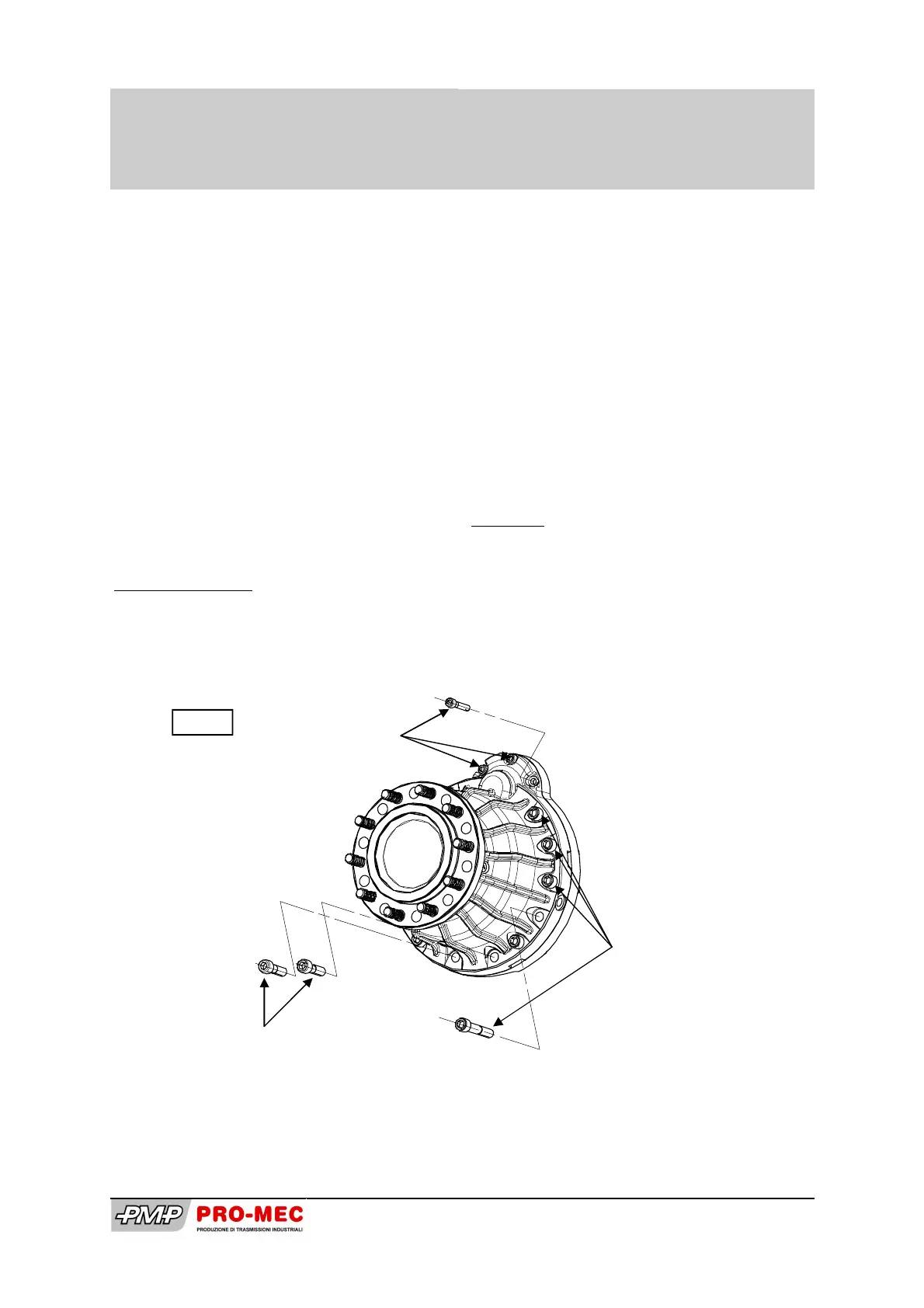
A questo punto è possibile rimontare il
pacco freni rispettando scrupolosamente i
passi indicati a pag. 12. Completata questa
operazione cospargere con del sigillante la
superficie di contatto sulla flangia (16/17),
quindi accostare il gruppo al corpo (7/8)
utilizzando le 4 spine (74) come guida.
Aiutarsi con un martello di gomma facendo
attenzione che il gruppo rimanga sempre in
asse al fine di non danneggiare le spine
stesse. Riposizionare nelle sedi corrette le
16 viti (81, 85, 86) e avvitarle con le
seguenti coppie di serraggio:
(81) viti M12 cl. 8.8 80 Nm
(85) viti M12 cl. 8.8 80 Nm
(86) viti M8 cl. 12.9 40 Nm
Rifornimento Olio
Per il rifornimento dell’olio seguire le
istruzioni a pag. 13.
Now is possible to assemble the brake disc
unit paying attention to respect the steps on
page 12. Then lay a coat of sealant on the
flange contact surface (16/17) and set the
gearbox to the casing (7/8) , centring on its 4
pins (74). Using a rubber hammer, beat gen-
tle the unit until it is completely inserted.
Now, insert the screws in their own holes
and set them with the following torque
wrenches:
(81) screw M12 cl. 8.8 80 Nm
(85) screw M12 cl. 8.8 80 Nm
(86) screw M8 cl. 12.9 40 Nm
Oil filling
Follow with great attention instructions on
page 13.
3 viti (86)
3 screws (86)
2 viti (81)
2 screws (81)
11 viti (85)
11 screws (85)
Fig 20
PMS701 HS-TR
STD VERSION
Disassemblaggio/assemblaggio
Disassembly / assembly